RM0016 Inter-integrated circuit (I
2
C) interface
Doc ID 14587 Rev 8 287/449
EV6_1: no associated flag event, used for 1 byte reception only. Program ACK=0 and STOP=1 after clearing ADDR.
EV7: RxNE=1, cleared by reading DR register.
EV7_1: RxNE=1, cleared by reading DR register, program ACK=0 and STOP request
EV9: ADD10=1, cleared by reading SR1 register followed by writing DR register.
2. If the DR and shift registers are full, the next data reception (I
2
C clock generation for slave) is performed after the EV7
event is cleared. In this case, EV7 does not overlap with data reception.
3. If a single byte is received, it is NA.
4. EV5, EV6 and EV9 events stretch SCL low until the end of the corresponding software sequence.
5. EV7 software sequence must be completed before the end of the current byte transfer.In case EV7 software sequence can
not be managed before the current byte end of transfer, it is recommended to use BTF instead of RXNE with the drawback
of slowing the communication.
6. The EV6_1 or EV7_1 software sequence must be completed before the ACK pulse of the current byte transfer.
7. See also: Note 8 on page 300.
Method 2: This method is for the case when the I2C is used with interrupts that do not have
the highest priority in the application or when the I2C is used with polling.
With this method:
● DataN_2 is not read, so that after DataN_1, the communication is stretched (both
RxNE and BTF are set).
● Then, the ACK bit must be cleared before reading DataN-2 in DR to make sure this bit
has been cleared before the DataN Acknowledge pulse.
● After that, just after reading DataN_2, software must set the STOP/ START bit and read
DataN_1. After RxNE is set, read DataN.
This is illustrated in the following figure:
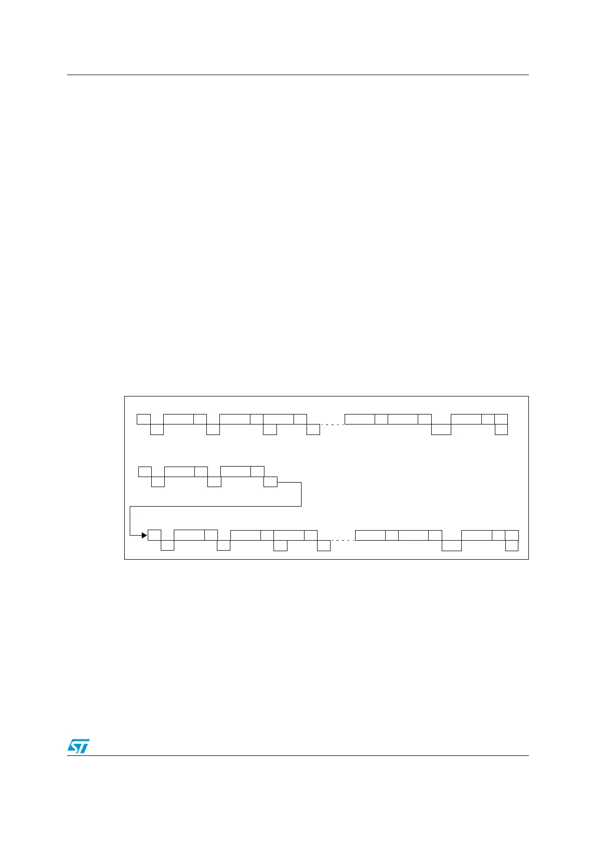
Figure 106. Method 2: transfer sequence diagram for master receiver when N >2
1. Legend:
S= Start, S
r
= Repeated Start, P= Stop, A= Acknowledge, NA= Non-acknowledge,
EVx= Event (with interrupt if ITEVTEN=1)
EV5: SB=1, cleared by reading SR1 register followed by writing the DR register.
EV6: ADDR1, cleared by reading SR1 register followed by reading SR3.
In 10-bit master receiver mode, this sequence should be followed by writing CR2 with START = 1.
EV7: RxNE=1, cleared by reading DR register.
EV7_2: BTF = 1, DataN-2 in DR and DataN-1 in shift register, program ACK = 0, Read DataN-2 in DR.
Program STOP = 1, read DataN-1.
EV9: ADD10= 1, cleared by reading SR1 register followed by writing DR register.
2. EV5, EV6 and EV9 events stretch SCL low until the end of the corresponding software sequence.
3. EV7 software sequence must be completed before the end of the current byte transfer. In case EV7
software sequence can not be managed before the current byte end of transfer, it is recommended to use
BTF instead of RXNE, with the drawback of slowing the communication.
AAddressS
EV5 EV6
AData1 AData2
EV7 EV7
ADataN-2 ADataN-1
EV7_2
NADataN
EV7
P
7- bit master receiver
10- bit master receiver
AHeaderS
EV5 EV9
AData1 AData2
EV7 EV7
ADataN-2 ADataN-1
EV7_2
NADataN
EV7
P
AAddress
EV6
AHeaderS
r
EV5
EV6

 Loading...


