16-bit advanced control timer (TIM1) RM0016
178/449 Doc ID 14587 Rev 8
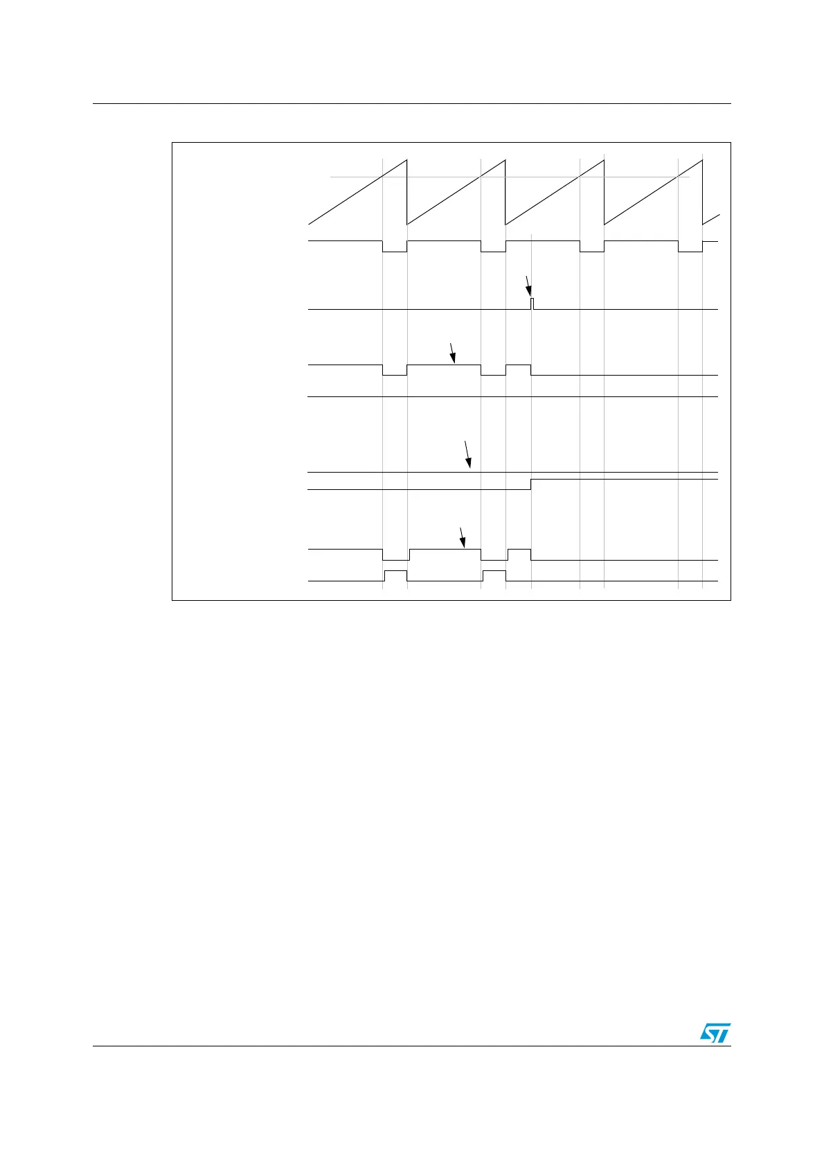
Figure 76. Six-step generation, COM example (OSSR = 1)
17.5.8 Using the break function
The break function is often used in motor control. When using the break function, the output
enable signals and inactive levels are modified according to additional control bits (MOE,
OSSR and OSSI bits in the TIM1_BKR register).
When exiting from reset, the break circuit is disabled and the MOE bit is low. The break
function is enabled by setting the BKE bit in the TIM1_BKR register. The break input polarity
can be selected by configuring the BKP bit in the same register. BKE and BKP can be
modified at the same time.
Because MOE falling edge can be asynchronous, a resynchronization circuit has been
inserted between the actual signal (acting on the outputs) and the synchronous control bit
(accessed in the TIM1_BKR register). It results in some delays between the asynchronous
and the synchronous signals. For example, if MOE is written to 1 after it has been low, a
delay (dummy instruction) must be inserted before it can be read correctly.
counter (CNT)
OCiREF
(CCRx)
OCi
OCiN
CCi
E=1
CCi
NE=0
OCiM=110 (PWM1)
Write
CCi
E to 0
Write COMG to 1
Commutation (COM)
CCi
E=1
CCi
NE=0
OCiM=100
OCi
OCiN
CCi
E=1
CCi
NE=0
OCiM=100 (forced inactive)
Write
CCi
NE to 1
CCi
E=0
CCi
NE=1
OCiM=101
OCi
OCiN
CCi
E=1
CCi
NE=1
OCiM=110 (PWM1)
Write
CCi
E and CxNE to 0
CCi
E=1
CCi
NE=0
OCiM=100
EXAMPLE 1
EXAMPLE 2
EXAMPLE 3

 Loading...


