Inter-integrated circuit (I
2
C) interface RM0016
288/449 Doc ID 14587 Rev 8
When 3 bytes remain to be read:
● RxNE = 1 => Nothing (DataN-2 not read).
● DataN-1 received
● BTF = 1 because both shift and data registers are full: DataN-2 in DR and DataN-1 in
the shift register => SCL tied low: no other data will be received on the bus.
● Clear ACK bit
● Read DataN-2 in DR => This launches the DataN reception in the shift register
● DataN received (with a NACK)
● Program START/STOP
● Read DataN-1
● RxNE = 1
● Read DataN
The procedure described above is valid for N>2. The cases where a single byte or two bytes
are to be received should be handled differently, as described below:
● Case of a single byte to be received:
– In the ADDR event, clear the ACK bit.
– Clear ADDR
– Program the STOP/START bit.
– Read the data after the RxNE flag is set.
● Case of two bytes to be received:
– Set POS and ACK
– Wait for the ADDR flag to be set
– Clear ADDR
–Clear ACK
– Wait for BTF to be set
–Program STOP
– Read DR twice
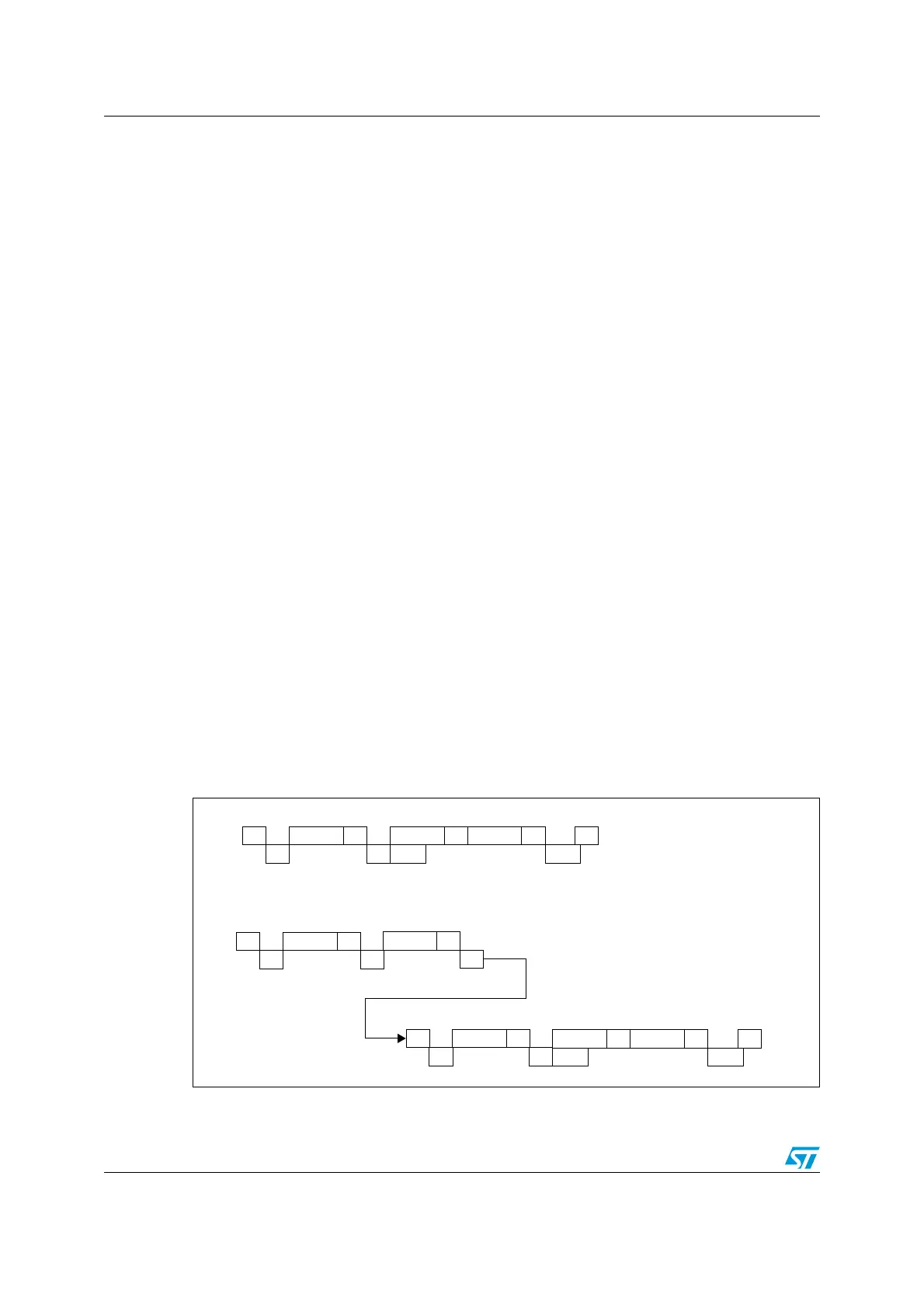
Figure 107. Method 2: transfer sequence diagram for master receiver when N=2
1. Legend:
AAddressS
EV5 EV6
AData1 Data2
EV7_3
NA P
EV6_1
7- bit master receiver
10- bit master receiver
AHeaderS
EV5 EV9
AAddress
EV6
AData1 Data2
EV7_3
NA P
EV6_1
AHeaderS
r
EV5
EV6

 Loading...


