Controller area network (beCAN) RM0016
374/449 Doc ID 14587 Rev 8
Note: In 32-bit configuration, the FMLx and FMHx bits must have the same value to ensure that
the four Mask/Identifier registers are in the same mode.
When a standard identifier is received (IDE bit is zero), the extended part of 32-bit or 16-bit
filters is not compared.
To filter a group of identifiers, configure the Mask/Identifier registers in mask mode.
To select single identifiers, configure the Mask/Identifier registers in identifier list mode.
Filters not used by the application should be left deactivated.
Each filter within a filter bank is numbered (called the Filter Number) from 0 to a maximum
dependent on the mode and the scale of each of the 6 filter banks.
For the filter configuration, refer to Figure 147 through Figure 150.
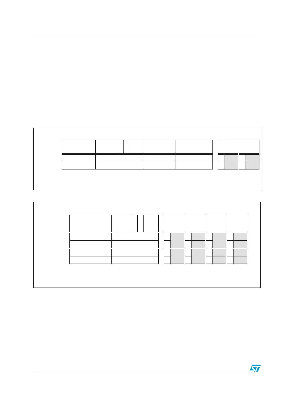
Figure 147. 32-bit filter bank configuration (FSCx bits = 0b11 in CAN_FCRx register)
Figure 148. 16-bit filter bank configuration (FSCx bits = 0b10 in CAN_FCRx register)
Filter registers Filter mode
1
Mapping
STID[10:3] /
EXID[28:21]
STID [2:0] /
EXID[20:18]
RTR
IDE
EXID
[17:15]
EXID [14:7] EXID[6:0] 0
FMHx = 0
FMLx = 0
FMHx = 1
FMLx = 1
Identifier CAN_FxR1 CAN_FxR2 CAN_FxR3 CAN_FxR4 ID
n
ID
n
Identifier/Mask CAN_FxR5 CAN_FxR6 CAN_FxR7 CAN_FxR8 M ID
n+1
ID= Identifier
M = Mask
n = Filter number
x = Filter bank number
1
The FMHx and FMLx bits are located in the CAN_FMR1 and CAN_FMR2 registers
Filter registers Filter mode
1
Mapping
STID[10:3] /
EXID[28:21]
STID [2:0]
/ EXID
[20:18]
RTR
IDE
EXID
[17:15]
FMHx = 0
FMLx = 0
FMHx = 0
FMLx = 1
FMHx = 1
FMLx = 0
FMHx = 1
FMLx = 1
Identifier CAN_FxR1 CAN_FxR2 ID
n
ID
nID
n
ID
n
Identifier/Mask CAN_FxR3 CAN_FxR4 M ID
n+1 M ID n+1
Identifier CAN_FxR5 CAN_FxR6 ID
n+1
ID
n+2
ID
n+1 ID n+2
Identifier/Mask CAN_FxR7 CAN_FxR8 M M ID
n+2 ID n+3
ID= Identifier
M = Mask
n = Filter number
x = Filter bank number
1
The FMHx and FMLx bits are located in the CAN_FMR1 and CAN_FMR2 registers

 Loading...


