RM0016 General purpose I/O ports (GPIO)
Doc ID 14587 Rev 8 107/449
11.3.1 Input modes
Clearing the DDRx bit selects input mode. In this mode, reading a IDR bit returns the digital
value of the corresponding I/O pin.
Refer to Section 11.7: Input mode details on page 108 for information on analog input,
external interrupts and Schmitt trigger enable/disable.
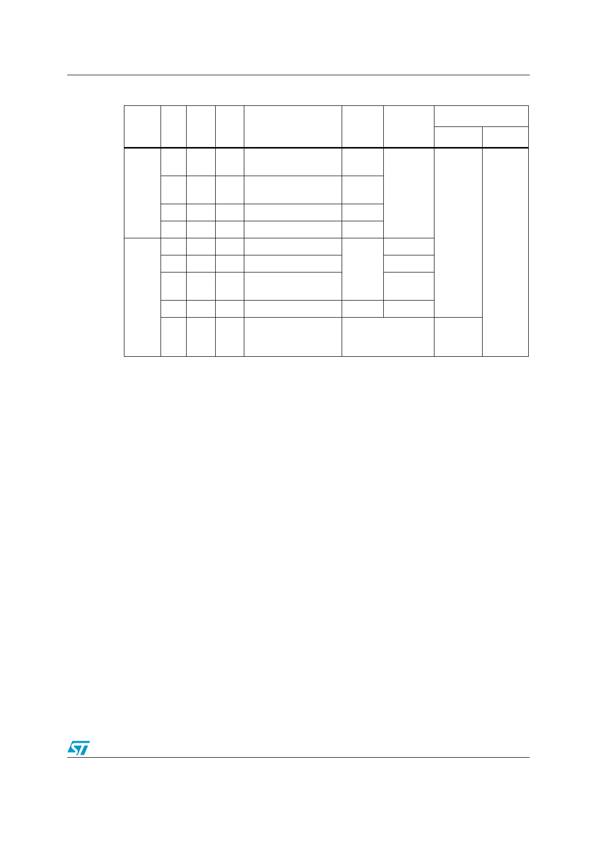
As shown in Ta bl e 2 1 , four different input modes can be theoretically be configured by
software: floating without interrupt, floating with interrupt, pull-up without interrupt or pull-up
with interrupt. However in practice, not all ports have external interrupt capability or pull-ups.
You should refer to the datasheet pin-out description for details on the actual hardware
capability of each port.
11.3.2 Output modes
Setting the DDRx bit selects output mode. In this mode, writing to the ODR bits applies a
digital value to the I/O through the latch. Reading IDR bit returns the digital value from the
corresponding I/O pin. Using the CR1, CR2 registers, different output modes can be
configured by software: Push-pull output, Open-drain output.
Refer to Section 11.8: Output mode details on page 109 for more information.
Table 21. I/O port configuration summary
Mode
DDR
bit
CR1
bit
CR2
bit
Function Pull-up P-buffer
Diodes
to V
DD
to V
SS
Input
00 0
Floating without
interrupt
Off
Off
On
(1)
1. In 3.6 V and 5 V tolerant I/Os, protection diode to V
DD
is not implemented.
On
01 0
Pull-up without
interrupt
On
0 0 1 Floating with interrupt Off
0 1 1 Pull-up with interrupt On
Output
1 0 0 Open drain output
Off
Off
1 1 0 Push-pull output On
10 1
Open drain output, fast
mode
Off
1 1 1 Push-pull, fast mode Off On
1x x
True open drain (on
specific pins)
Not implemented
Not im-
plemented
(2)
2. The diode connected to V
DD
is not implemented in true open drain pads. A local protection between the
pad and V
OL
is implemented to protect the device against positive stress.

 Loading...


