RM0016 Analog/digital converter (ADC)
Doc ID 14587 Rev 8 417/449
24.5.6 Analog watchdog
The analog watchdog is enabled for single conversion and non-buffered continuous
conversion modes by setting the AWDEN bit in the ADC_CSR register.
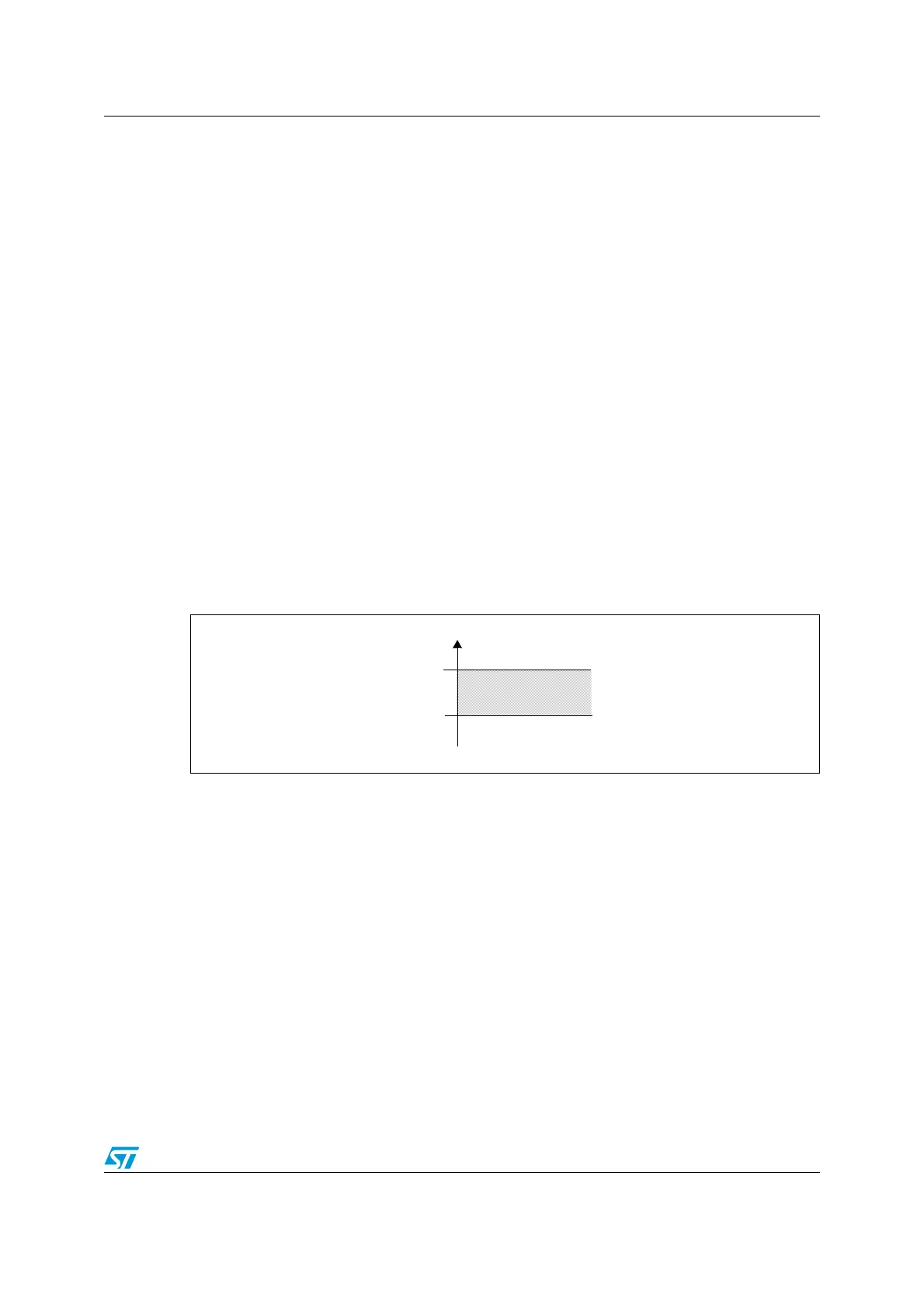
The AWD analog watchdog flag is set if the analog voltage converted by the ADC is below a
low threshold or above a high threshold as shown in Figure 160. These thresholds are
programmed in the ADC_HTR and ADC_LTR 10-bit registers. An interrupt can be enabled
by setting the AWDIE bit in the ADC_CSR register.
For Scan mode, the analog watchdog can be enabled on selected channels using the
AWENx bits in the ADC_AWCRH and ADC_AWCRL registers. The watchdog status for
each channel is obtained by reading the AWSx bits in the ADC_AWSRH and ADC_AWSRL
registers. If any of the AWS flags are set, this also sets the AWD flag. Depending on the
AWDIE interrupt enable bit, an interrupt is generated at the end of the SCAN sequence. The
interrupt routine should then clear the AWS flag and the global AWD flag in the ADC_CSR
register.
For Buffered continuous mode, the analog watchdog can be enabled on selected buffers,
and is managed as described for scan mode, with the difference the buffers contain the
results of continuous conversions performed on a single channel.
Refer to Section 24.7 for more details on interrupts.
Note: To optimize analog watchdog interrupt latency in scan or buffered continuous mode, it
recommended to use the last channels in the conversion sequence.
Figure 160. Analog watchdog guarded area
Analog voltage
High threshold
Low threshold
Guarded area
HTR
LTR

 Loading...


