RM0016 Universal asynchronous receiver transmitter (UART)
Doc ID 14587 Rev 8 325/449
It exits from mute mode when an address character is received which matches the
programmed address. Then the RWU bit is cleared and subsequent bytes are received
normally. The RXNE bit is set for the address character since the RWU bit has been cleared.
The RWU bit can be written to 0 or 1 when the receiver buffer contains no data (RXNE=0 in
the UART_SR register). Otherwise the write attempt is ignored.
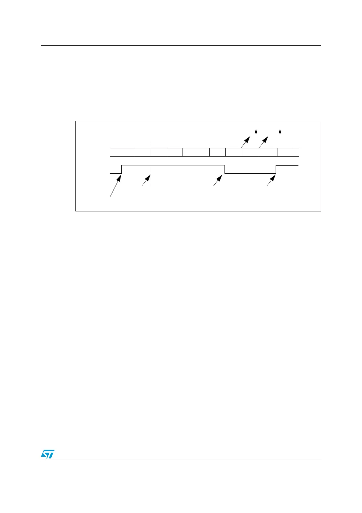
An example of mute mode behavior using address mark detection is given in Figure 120.
Figure 120. Mute mode using Address mark detection
Note: If parity control is enabled, the parity bit remains in the MSB and the address bit is put in the
"MSB - 1" bit.
For example, with 7-bit data, address mode and parity control:
SB I 7-bit data I ADD I PB I STB
where:
SB = Start Bit
STB = Stop Bit
ADD = Address bit
PB = Parity Bit
22.3.8 LIN (local interconnection network) mode
The UART supports LIN break and delimiter generation in LIN master mode.
Refer to Section 22.4.1: Master mode on page 333 for details. LIN slave mode is supported
by the UART2 and 3 only, not by UART1.
LIN mode is selected by setting the LINEN bit in the UART_CR3 register. In LIN mode, the
following bits must be kept cleared:
● CLKEN, STOP[1:0] in the UART_CR3 register
● SCEN, HDSEL and IREN in the UART_CR5 register
RWU written to 1
IDLE
RX
Addr=0
RWU
Mute Mode Normal Mode
Matching address
RXNE RXNE
(RXNE was cleared)
Data 2 Data 3 Data 4 Data 5Data 1 IDLE Addr=1 Addr=2
Mute Mode
In this example, the current address of the receiver is 1
(programmed in the UART_CR4 register)
Non-matching address
Non-matching address

 Loading...


