16-bit general purpose timers (TIM2, TIM3, TIM5) RM0016
220/449 Doc ID 14587 Rev 8
18.4.3 Capture/compare channels
Input stage
Refer to Section 17.5: TIM1 capture/compare channels on page 163.
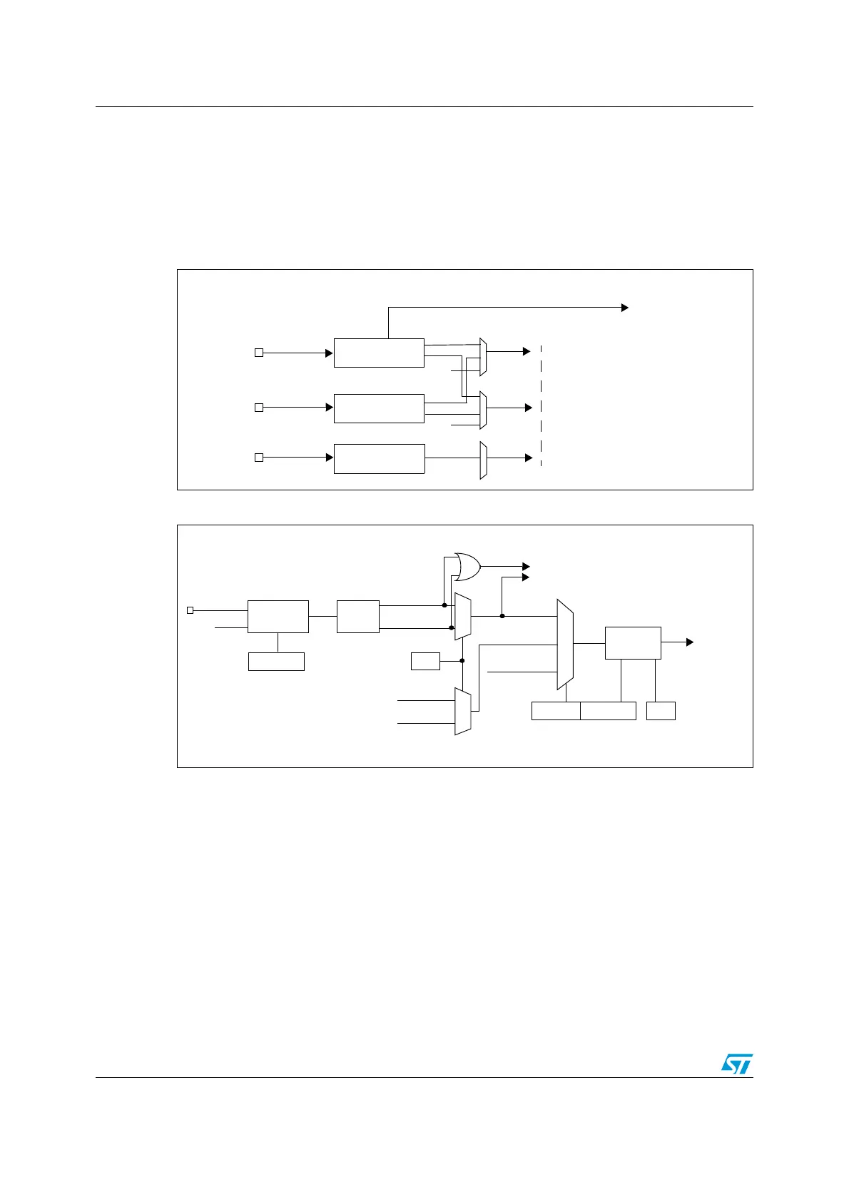
There are two input channels, as shown in Figure 85: Input stage block diagram.
Figure 85. Input stage block diagram
Figure 86. Input stage of TIM 2 channel 1
IC1
IC2
Input Filter &
Edge Detector
TI1FP1
TRC
TRC
TI1FP2
TI2FP1
TI2FP2
TI1
TI2
TIMx_CH1
TIMx_CH2
to clock/trigger controller
TRC
TI1F_ED
to capture/compare channels
Input Filter &
Edge Detector
IC3
TI3
TIMx_CH3
Input Filter &
Edge Detector
TI1
0
1
TIM2_CCER1
CC1P
divider
/1, /2, /4, /8
ICPS[1:0]
TI1F_ED
filter
ICF[3:0]
down-counter
TIM2_CCMR1
Edge
Detector
TI1F_rising
TI1F_falling
to the clock/trigger controller
TI1FP1
11
01
TIM2_CCMR1
CC1S[1:0]
IC1
TI2FP1
TRC
(from channel 2)
(from clock/trigger
controller)
10
f
MASTER
TIM2_CCER1
CC1E
ICPS
TI1F
0
1
TI2F_rising
TI2F_falling
(from channel 2)

 Loading...


