16-bit advanced control timer (TIM1) RM0016
150/449 Doc ID 14587 Rev 8
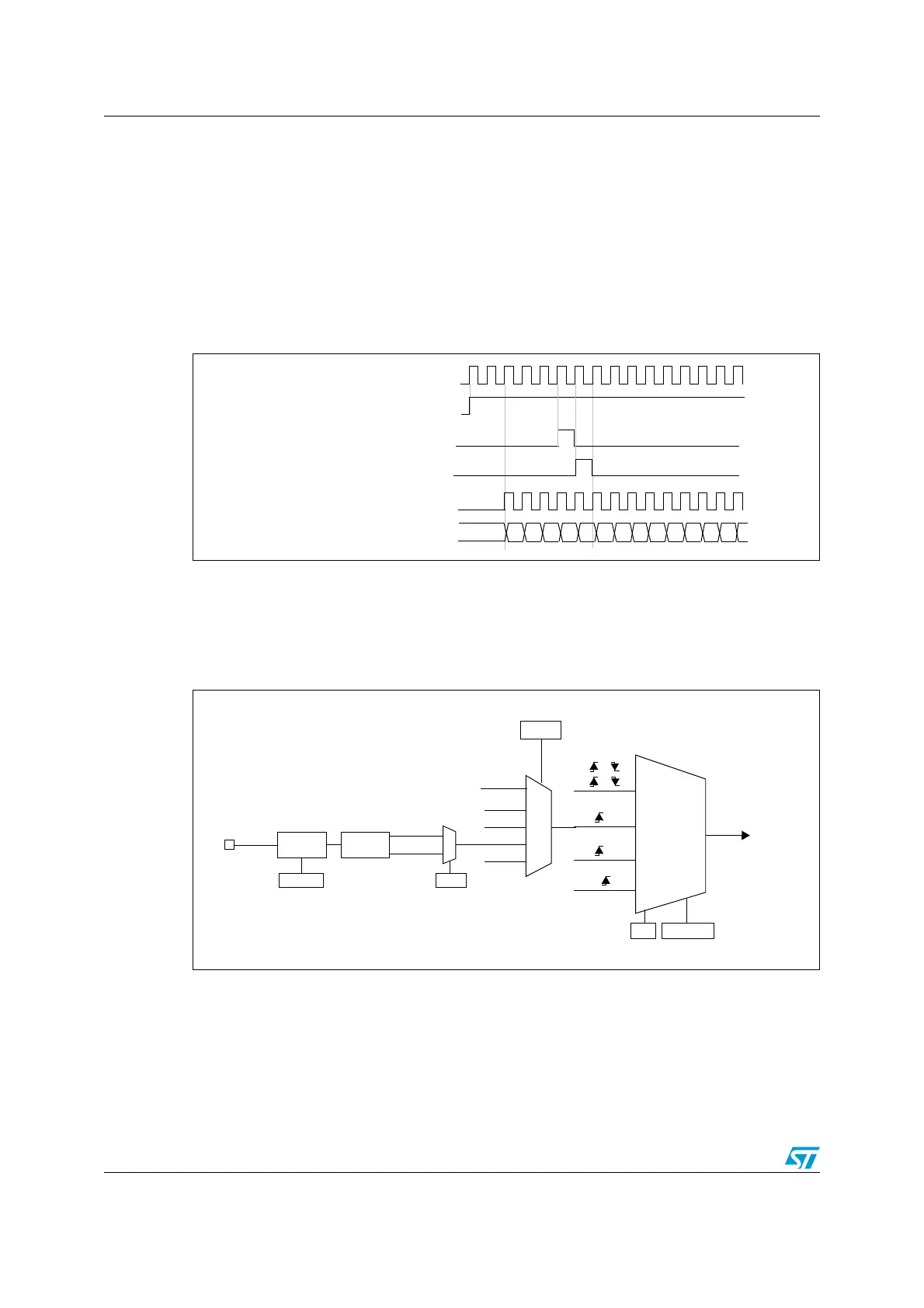
17.4.2 Internal clock source (f
MASTER
)
If both the clock/trigger mode controller and the external trigger input are disabled
(SMS = 000 in TIM1_SMCR and ECE = 0 in the TIM1_ETR register), the CEN, DIR, and UG
bits behave as control bits and can be changed only by software (except UG which remains
cleared automatically). As soon as the CEN bit is written to 1, the prescaler is clocked by the
internal clock.
The figure below shows the behavior of the control circuit and the up-counter in normal
mode, without the prescaler.
Figure 44. Control circuit in normal mode, f
CK_PSC
= f
MASTER
17.4.3 External clock source mode 1
The counter can count at each rising or falling edge on a selected timer input. This mode is
selected when SMS = 111 in the TIM1_SMCR register (see Figure 45).
Figure 45. TI2 external clock connection example
f
MASTER
00
COUNTER CLOCK = CK_CNT = CK_PSC
COUNTER REGISTER
01 02 03 04 05 06 0732 33 34 35 3631
CEN = CNT_EN
UG
CNT_INIT (=UG synchronized: UG or UG+1 clock)
f
MASTER
Encoder
mode
External clock
mode 1
External clock
mode 2
Internal clock
mode
ETRF
TRGI
TI1F
TI2F
or
or
or
(internal clock)
CK_PSC
TIM1_ETR
ECE
TIM1_SMCR
SMS[2:0]
TI1F_ED
TI1FP1
TI2FP2
ETRF
TIM1_SMCR
TS[2:0]
TI2
0
1
TIM1_CCER1
CC2P
Filter
ICF[3:0]
TIM1_CCMR2
Edge
Detector
ti2f_rising
ti2f_falling
110
100
101
111
TRGO from other timers

 Loading...


