RM0016 Independent watchdog (IWDG)
Doc ID 14587 Rev 8 123/449
Timeout period
The timeout period can be configured through the IWDG_PR and IWDG_RLR registers. It
is determined by the following equation:
where:
T = Timeout period
T
LSI
= 1/f
LSI
P = 2
(PR[2:0] + 2)
R = RLR[7:0]+1
The IWDG counter must be refreshed by software before this timeout period expires.
Otherwise, an IWDG reset will be generated after the following delay has elapsed since the
last refresh operation:
D = T + 6 x T
LSI
where D= delay between the last refresh operation and the IWDG reset.
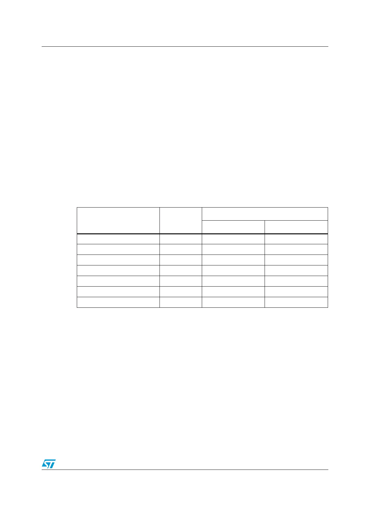
Table 28. Watchdog timeout period (LSI clock frequency = 128 kHz)
Prescaler divider PR[2:0] bits
Timeout
RL[7:0]= 0x00 RL[7:0]= 0xFF
/4 0 62.5 µs 15.90 ms
/8 1 125 µs 31.90 ms
/16 2 250 µs 63.70 ms
/32 3 500 µs 127 ms
/64 4 1.00 ms 255 ms
/128 5 2.00 ms 510 ms
/256 6 4.00 ms 1.02 s

 Loading...


