16-bit general purpose timers (TIM2, TIM3, TIM5) RM0016
218/449 Doc ID 14587 Rev 8
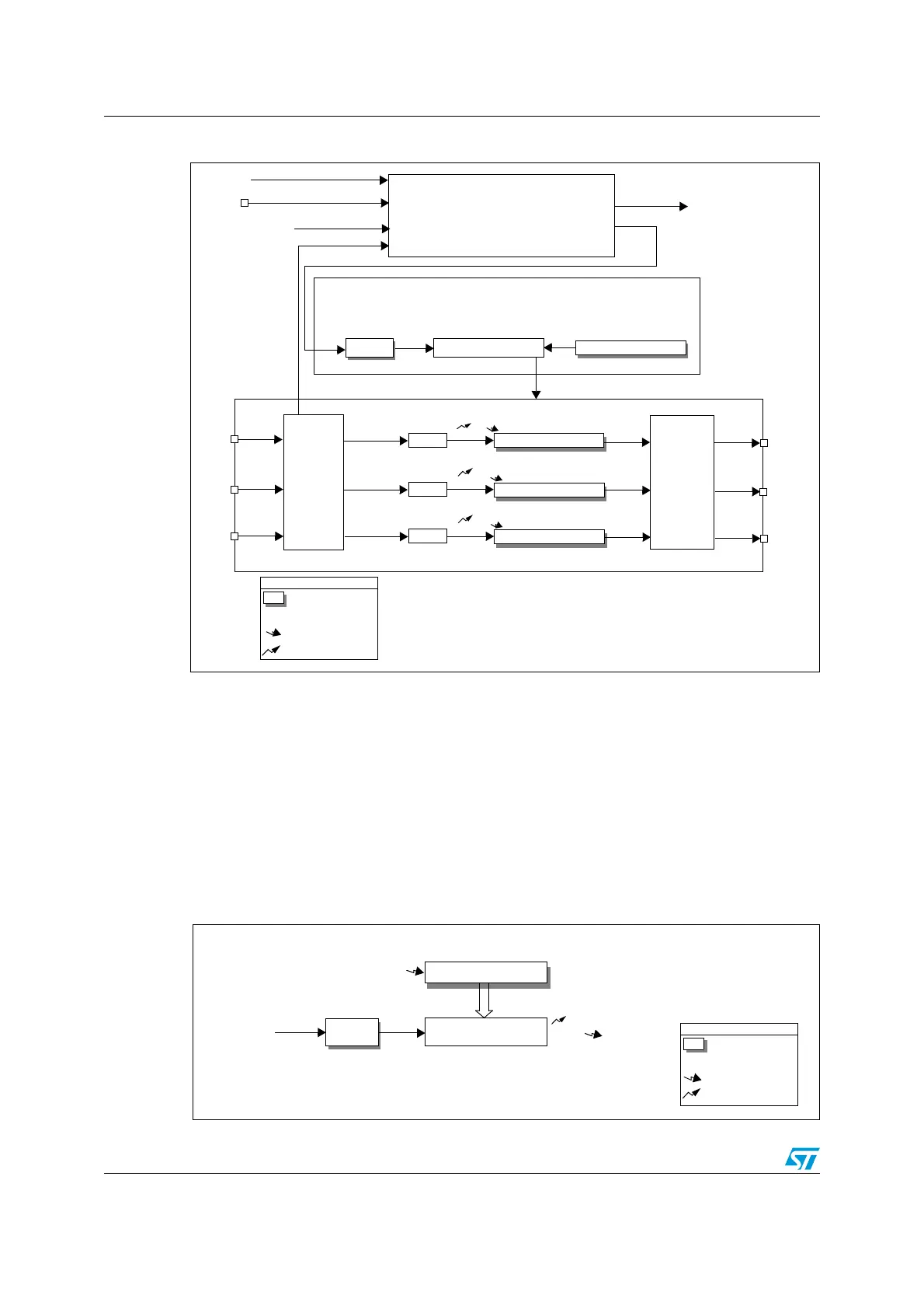
Figure 83. TIM5 block diagram
18.4.1 Time base unit
The timer has a time base unit that includes:
● 16-bit up counter
● 16-bit auto-reload register
● 4-bit programmable prescaler
There is no repetition counter.
The clock source for is the internal clock (f
MASTER
). It is connected directly to the CK_PSC
clock that feeds the prescaler driving the counter clock CK_CNT.
Figure 84. Time base unit
Prescaler
Auto-reload register
UP-DOWN COUNTER
Capture/Compare 1 Register
Capture/Compare 2 Register
UEV
f
MASTER
OC1REF
OC2REF
CK_PSC
IC1
IC2
Prescaler
Prescaler
IC2PS
IC1PS
CC1I
CC2I
TIM5_CH2
OC1
OC2
CK_CNT
UEV
TIME BASE UNIT
CLOCK/TRIGGER CONTROLLER
INPUT
OUTPUT
CAPTURE COMPARE ARRAY
TI1
TI2
TIM5_CH2
TIM5_CH1
STAGE
STAGE
TIM5_CH1
INTx
TRGO from other TIM timers
TRGO to TIM1/TIM6 timers
Reg
event
Legend:
Preload registers transferred
to shadow registers on update
interrupt
event (UEV) according to
control bit
TRC
Capture/Compare 3 Register
OC3REF
IC3
Prescaler
IC3PS
CC3I
TIM5_CH3
OC3
UEV
TI3
TIM5_CH3
Clock/reset/enable
ETR
TIM1_ETR
Prescaler
Auto-Reload Register
16-bit Counter
CK_PSC
CK_CNT
TIMx_PSCR
TIMx_CNTRH, CNTRL
TIMx_ARRH, ARRL
UEV
UIF
UEV
Reg
event
Legend:
Preload registers transferred
to shadow registers on update
control bit
interrupt
event (
UEV)
according to

 Loading...


