560
Upgrade and Maintenance Manual TX2560 M2 / RX2560 M2
Note for LAN connectors on dynamic LoM modules
The LAN connectors on the dynamic LoM modules are numbered in ascending
order from right to left beginning with “0”. The rightmost connector (LAN 0) is the
shared LAN connector respectively.
Depending on BIOS settings, the shared LAN connector may also be used as
a management LAN connector. For further information, please refer to the
corresponding BIOS Setup Utility reference manual.
I
Some of the devices that can be connected may require the installation
and setting up of special software (e.g. drivers) (see the documentation
for the connected device).
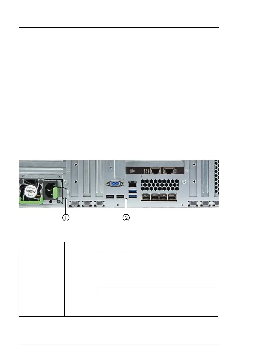
17.2.3.2 Indicators on the I/O panel
ID, CSS and Global Error indicators
Figure 428: ID, CSS and Global Error indicators
Pos. Label Indicator Status Description
1 ID
ID indicator,
see also
"iRMC-
related
status
signals" on
page 562
blue on
The server has been highlighted
using ServerView Operations
Manager, iRMC web frontend or the
ID button on the front panel for easy
identification
blue
flashing
The server has been highlighted for
easy identification using the iRMC
(AVR) with disabled local VGA
output.
 Loading...