Getting Started
23
M4300 Series and M4300-96X Fully Managed Switches User Manual
The following table describes the naming convention for all interfaces available on the switch.
Slot and Port Numbering for Switch Model M4300-96X
For switch model M4300-96X, the slots in the upper row of the chassis are numbered 1
through 6 from left to right. These slots can support PoE. The slots in the lower row of the
chassis are numbered 7 through 12 from left to right. These slots do not support PoE.
The port numbering depends on the port card.
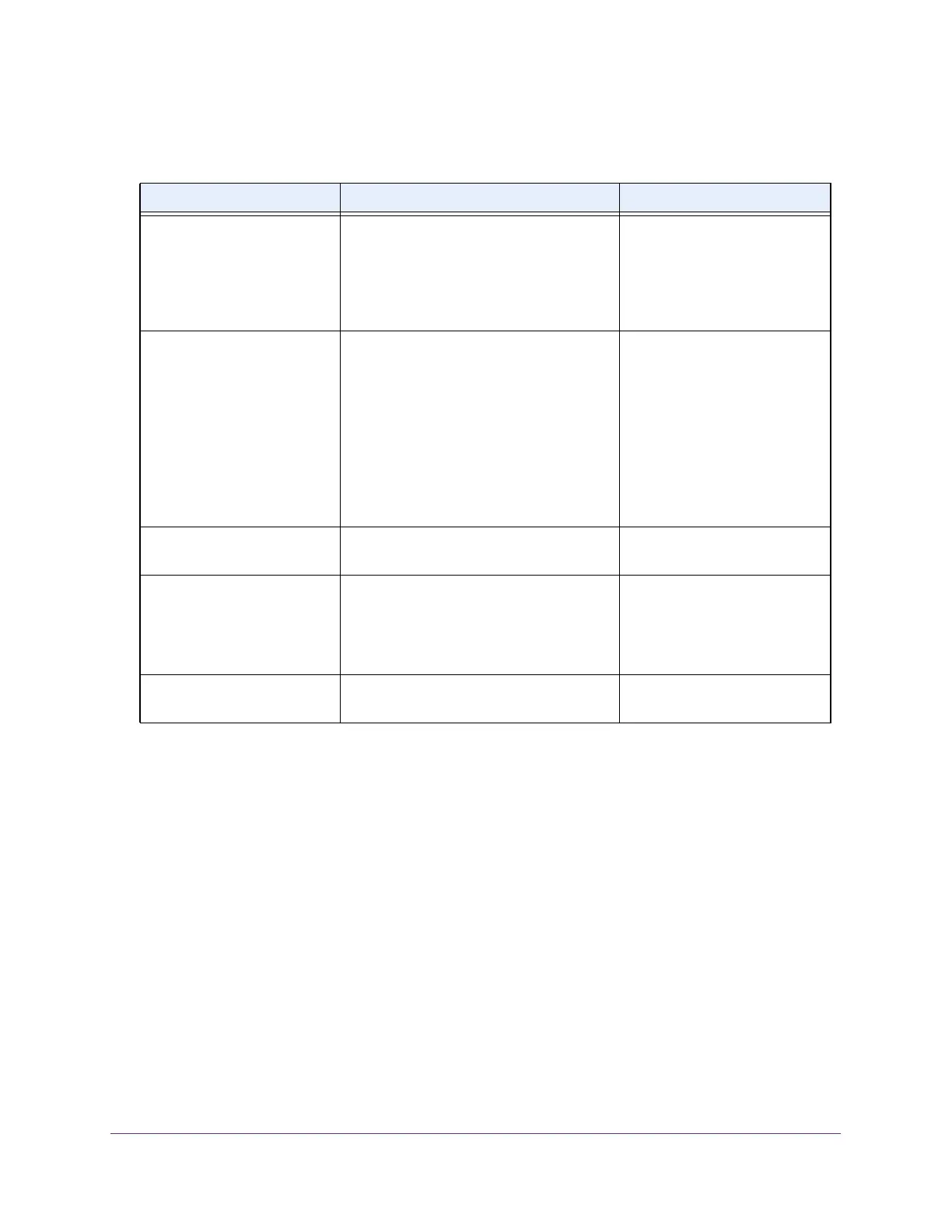
Table 3. Naming conventions for interfaces
Interface Description Example
Physical interfaces for all
M4300 switch models except
for model M4300-96X
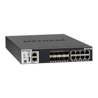
The physical ports are Gigabit Ethernet or
multispeed 10G Ethernet interfaces. The
interface number consists of the switch unit
number from 1 to 8, the slot number (which
is always 0), and the port number
, which is
a sequential number starting from 1.
1/0/1, 1/0/2, 1/0/3, and so on
2/0/1, 2/0/2, 2/0/3, and so on
3/0/1, 3/0/2, 3/0/3, and so on
Physical interfaces for model
M4300-96X
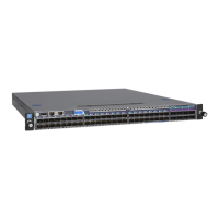
The physical ports are Gigabit Ethernet,
multispeed 10G Ethernet, or 40G Ethernet
interfaces.
The interface number consists of
the switch unit number from 1 to 8, the port
card number from 1 to 12, and the port
number from 1 to 8.
Note: The numbering for the APM402XL
40G port card differs (see
Slot and Port
Numbering on the
APM402XL Port Card on
page 24).
See Slot and Port Numbering for
Switch Model M4300-96X
on
page 23.
Link aggregation group (LAG) LAG interfaces are logical interfaces that
are used only for bridging functions.
LAG 1, LAG 2, LAG 3, and so on
CPU management interface This is the internal switch interface
responsible for the switch base MAC
address.
This interface is not configurable
and is always listed in the MAC
Address
Table.
0/15/1
Routing VLAN interfaces This is an interface used for routing
functionality
.
VLAN 1, VLAN 2, VLAN 3, and
so on