Configuration Examples
697
M4300 Series and M4300-96X Fully Managed Switches User Manual
MSTP Example Configuration
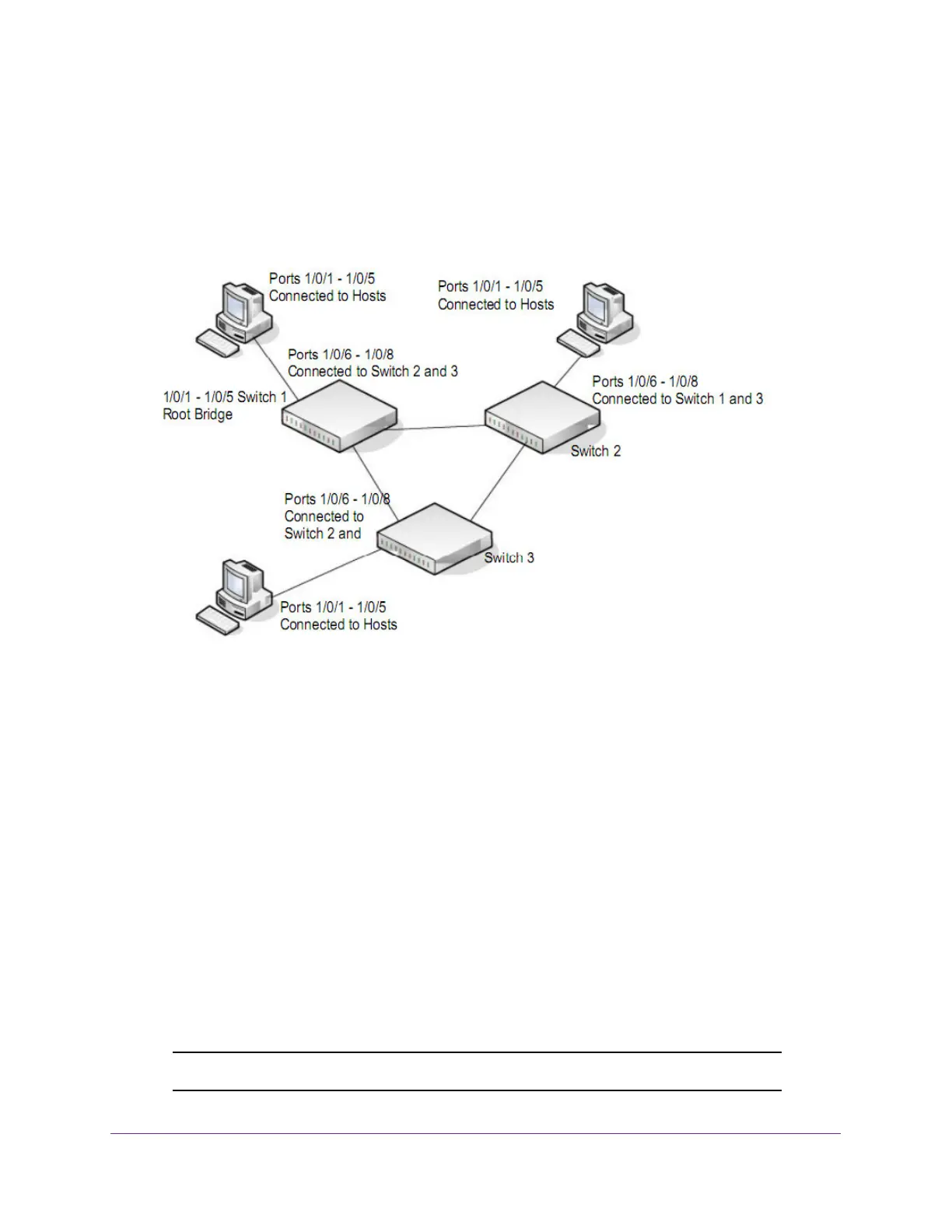
This example shows how to create an MSTP instance on the switch. The example network
includes three different switches that serve different locations in the network. In this example,
ports 1/0/1-1/0/5 are connected to host stations, so those links are not subject to network
loops. Ports 1/0/6–1/0/8 are connected across switches 1, 2 and 3.
Figure 2. MSTP sample configuration
Perform the following procedures on each switch to configure MSTP:
1. Use the VLAN Configuration page to create VLANs 300 and 500 (see Configure Basic
VLAN Settings on page 178).
2. Use the VLAN Membership page to include ports 1/0/1–1/0/8 as tagged (T) or untagged (U)
members of VLAN 300 and VLAN 500 (see Configure Basic VLAN Settings on page 178).
3. From the STP Configuration page, enable the Spanning
T
ree State option (see Configure
Advanced STP Settings on page 212).
Use the default values for the rest of the STP configuration settings. By default, the STP
Operation mode is MSTP and the Configuration Name is the switch MAC address.
4. From the CST Configuration page, set the Bridge Priority value for each of the three
switches to force Switch 1 to be the root bridge:
• Switch 1: 4096
• Switch 2: 12288
• Switch 3: 20480
Note: Bridge priority values are multiples of 4096.