Color Liquid Crystal Display Controller LH79524/LH79525 User’s Guide
4-6 Version 1.0
4.3.4 Pixel Serializer
The pixel serializer reads the 32-bit-wide LCD data from the output port of the LCD DMA
FIFO and extracts 12, 8, 4, 2, or 1 bits per pixel (bpp) data, depending on the operating
mode. In Dual Panel Mode, data alternately is read from the upper and lower LCD DMA
FIFOs. Depending on the operating mode, the extracted data is either used to point to a
color/grayscale value in the palette RAM or directly applied to an LCD panel input.
4.3.5 How Pixels are Stored in Memory
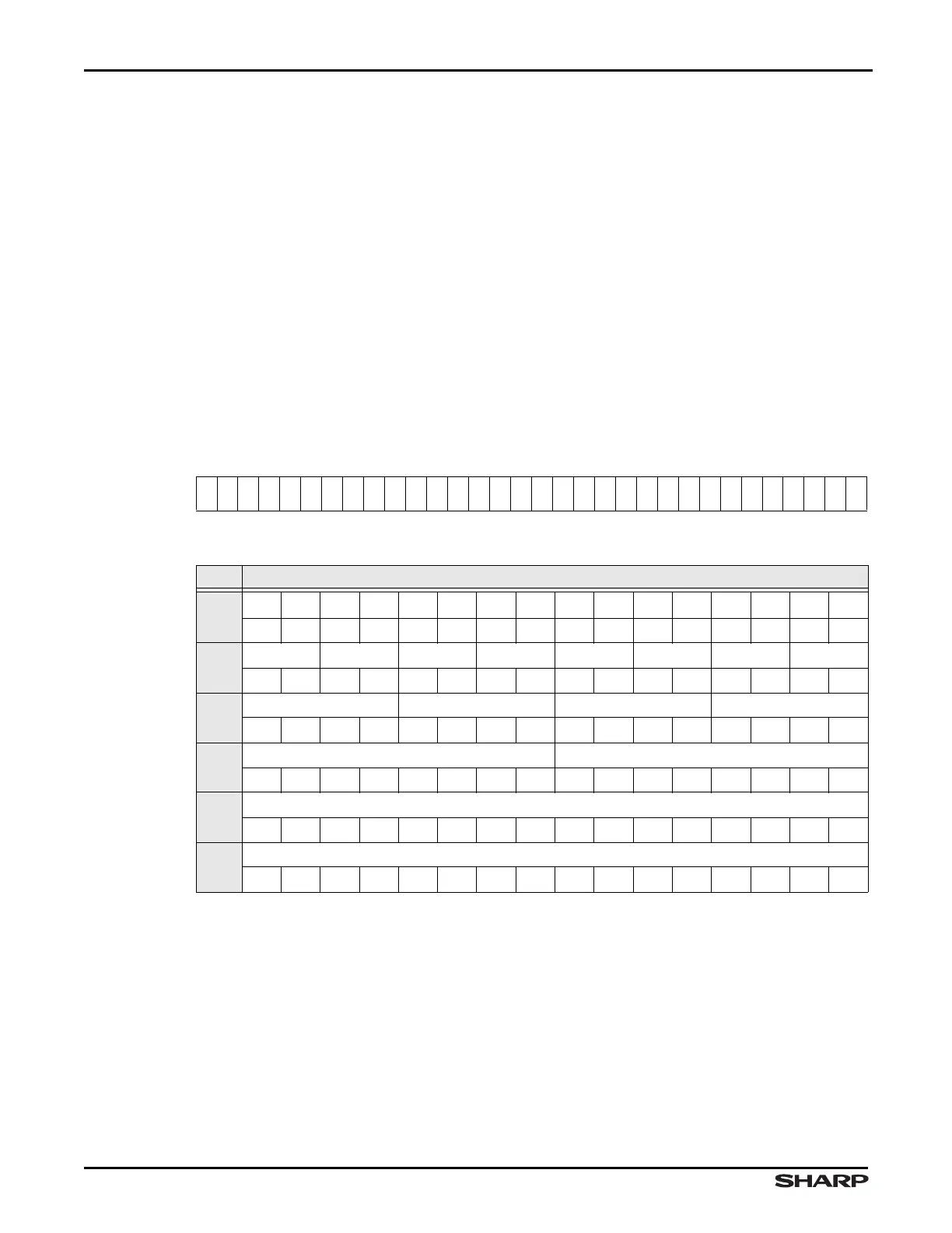
Table 4-1 shows the pixel arrangement on a display, with the first 32 pixels labeled p0
through p31. Table 4-2 and Table 4-3 show the data structure in each DMA FIFO word cor-
responding to the bpp combinations. The required data for each panel display pixel must
be extracted from the data word. The first pixel value in the frame corresponds to the color
value encoded in P0 (see Table 4-3), the second corresponds to P1, the third to P2, and
so on (continuing in Table 4-2).
NOTES:
1. LH79525 with 12-Bit CLCDC
2. LH79524 with 16-Bit CLCDC
Table 4-1. Pixel Display Arrangement
p0
p1
p2
p3
p4
p5
p6
p7
p8
p9
p10
p11
p12
p13
p14
p15
p16
p17
p18
p19
p20
p21
p22
p23
p24
p25
p26
p27
p28
p29
p30
p31
Table 4-2. Frame Buffer Pixel Storage Format [31:16]
BPP DMA FIFO OUTPUT BITS
1
31 30 29 28 27 26 25 24 23 22 21 20 19 18 17 16
p31 p30 p29 p28 p27 p26 p25 p24 p23 p22 p21 p20 p19 p18 p17 p16
2
p15 p14 p13 p12 p11 p10 p9 p8
1010101010101010
4
p7 p6 p5 p4
3210321032103210
8
p3 p2
7654321076543210
12
1
p1
111098 7654 3210
16
2
p1
1514131211109876543210