LH79524/LH79525 User’s Guide Universal Serial Bus Device
Version 1.0 17-19
17.2.3 Indexed Registers
The next group of registers in the USB Device are Indexed. Each IN endpoint and each
OUT Endpoint have their own set of control/status registers. Only one set of IN control and
status registers and one set of OUT control and status registers appear in the memory map
at any one time. Before accessing an endpoint’s control/status registers, the endpoint
number must be written to the INDEX register so that the correct control/status registers
appear in the memory map.
For example, to access INCSR1 (offset 0x44) for Endpoint 1, first write 0x1 to the INDEX
register, then read or write INCSR1. To access INCSR1 for Endpoint 3, first write 0x3 to
the INDEX register, then read or write INCSR1.
17.2.3.1 Index Register (INDEX)
The INDEX register determines which endpoint control/status registers are accessed at
address offsets 0x040 to 0x05C.
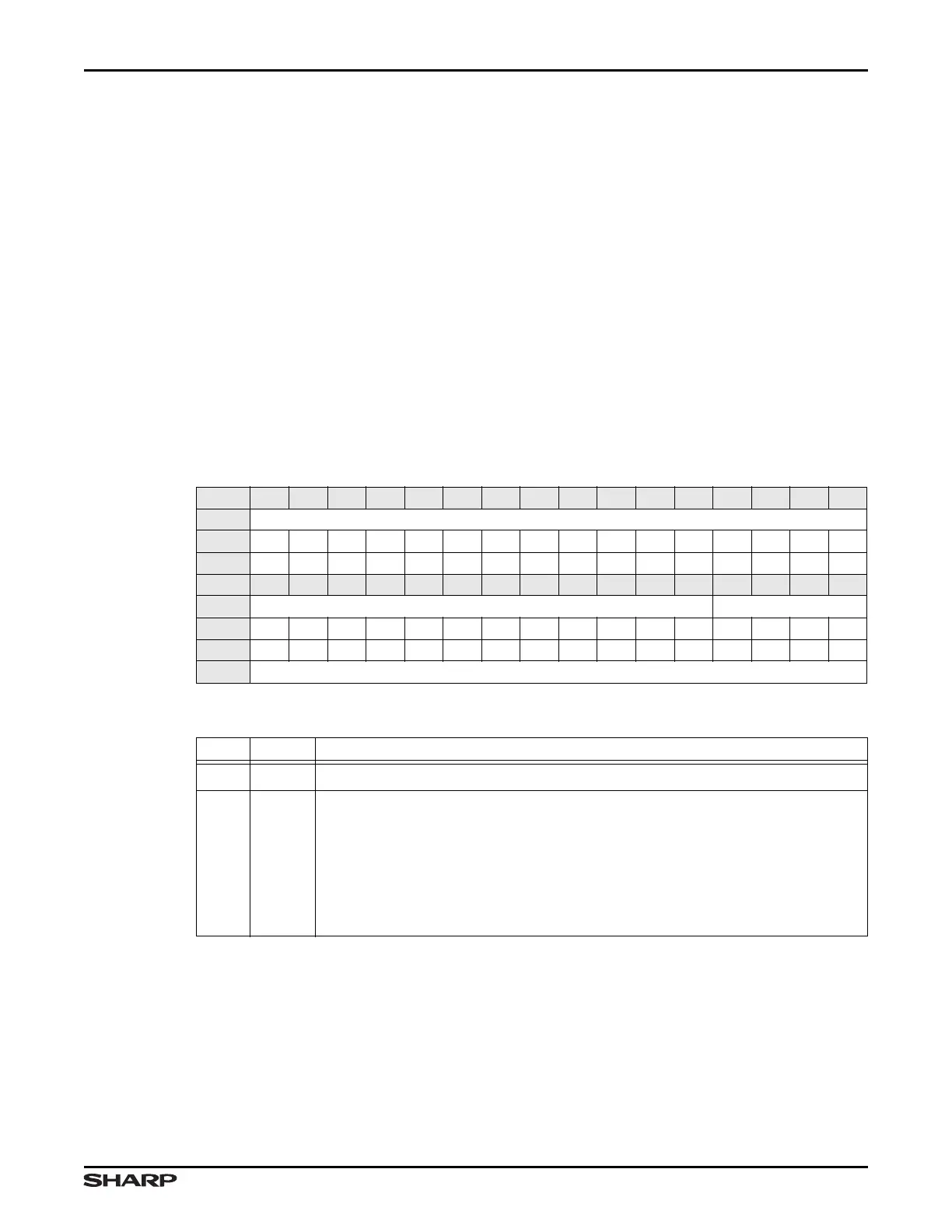
Table 17-24. INDEX Register
BIT 31 30 29 28 27 26 25 24 23 22 21 20 19 18 17 16
FIELD ///
RESET 0000000000000000
RW RO RO RO RO RO RO RO RO RO RO RO RO RO RO RO RO
BIT 15 14 13 12 11 10 9 8 7 6 5 4 3 2 1 0
FIELD /// INDEX
RESET 0000000000000000
TYPE RO RO RO RO RO RO RO RO RO RO RO R RW RW RW RW
ADDR 0xFFFF5000 + 0x038
Table 17-25. INDEX Fields
BITS NAME FUNCTION
31:4
/// Reserved Reading returns 0. Write the reset value.
3:0 INDEX
End Point Index This field specifies, by INDEX offset, which endpoint for the
particular register will be accessed by the next software read or write. The Index
values are:
0b0011 = EP3
0b0010 = EP2
0b0001 = EP1
0b0000 = EP0