I
2
S Converter LH79524/LH79525 User’s Guide
10-6 Version 1.0
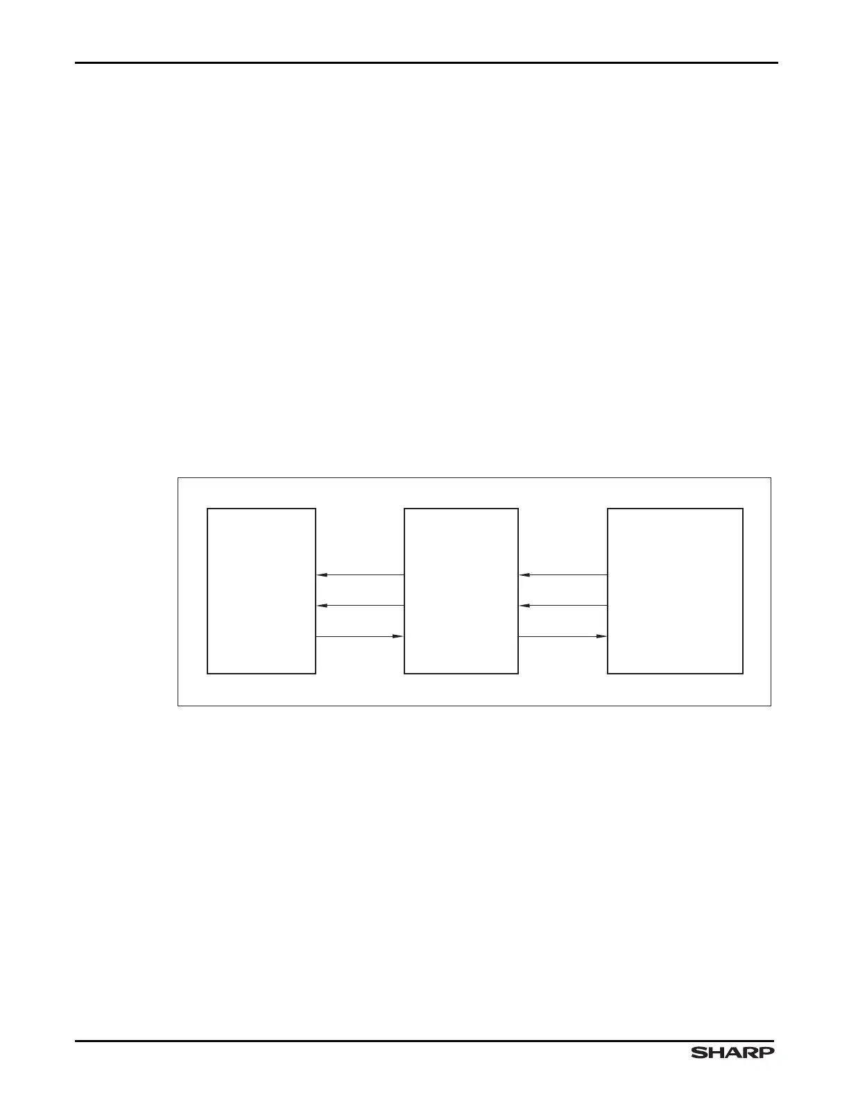
10.1.3.2 Slave Mode Transmission
During Slave Mode transmission, the I
2
S converter receives its clock (PB3/SSPCLK/I2SCLK)
and frame input (PB2/SSPFRM/I2SWS) from the external CODEC. In response to the exter-
nal CODEC signals, the I
2
S transmits data on the PB5/SSPTX/I2STXD/UARTTX0/
UARTIRTX0 pin.
The slave mode clock received by the SSP is the I
2
S slave mode clock input,
PB3/SSPCLK/I2SCLK, inverted as indicated by the CTRL:CLKINV bit.
The frame input received by the I
2
S converter is converted to a pulse and sent to the SSP
on SSPFSSIN. This conversion is accomplished by generating a pulse to the SSP for
every edge detected on PB2/SSPFRM/I2SWS. If WSDEL is set to 0, then the pulse is
delayed by 1 clock. In this case, the data cannot be received from the SSP and transmitted
to the external CODEC in time, as depicted by Figure 10-7. For this reason, the data
received from the SSP in slave mode is delayed by the I
2
S converter before being
transmitted on the PB5/SSPTX/I2STXD/UARTTX0/UARTIRTX0 pin. This results in a
one-frame lag in the transmission of data in slave mode, regardless of the value of
CTRL:WSDEL. Until the delay pipe is filled, the External Codec will receive a 0 on the
PB5/SSPTX/I2STXD/UARTTX0/UARTIRTX0 pin.
Figure 10-7. I
2
S Slave Mode Transmission Block Diagram
LH79525-97
SSP
(SLAVE)
EXTERNAL CODEC
(MASTER)
I2SCLKIN
I
2
S CONVERTER
(SLAVE)
I2SFSSIN
SCK
WS
SD
I2STXD
SSPCLKIN
SSPFSSIN
SSPTXD