LH79524/LH79525 User’s Guide Universal Serial Bus Device
Version 1.0 17-31
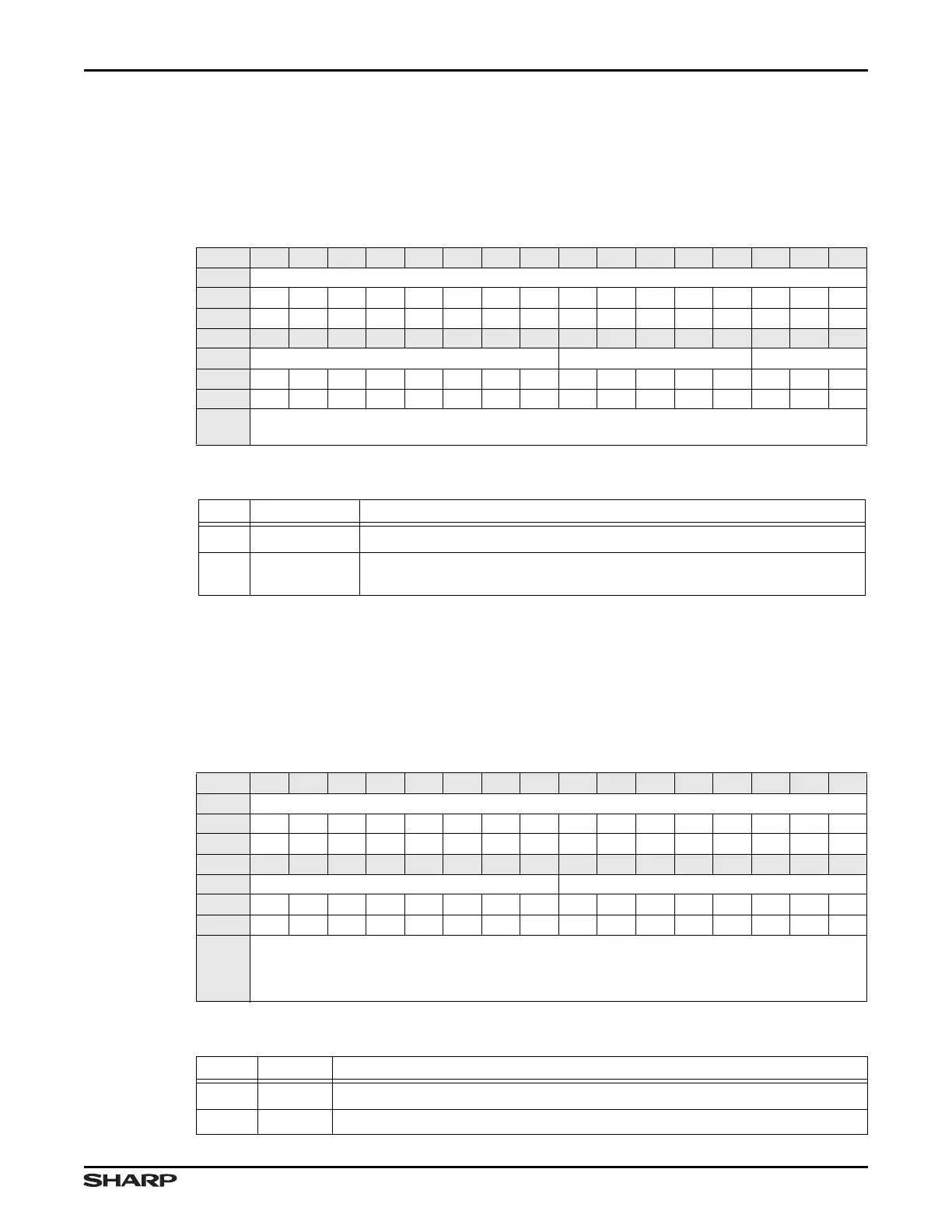
17.2.3.11 Out Count 2 Register (OUTCOUNT2)
OUTCOUNT2 is a read-only register that holds the upper 3 bits of the number of received
data bytes in the packet in the FIFO associated with the currently-selected OUT endpoint.
The value returned is valid while OUT_PKT_RDY (OUTCSR1.D0) is set.
17.2.3.12 FIFOs for Endpoints 0-3 (FIFOx)
These 4 addresses provide CPU access to the FIFOs for each endpoint. Writing to these
addresses loads data into the IN FIFO for the corresponding endpoint. Reading from these
addresses unloads data from the OUT FIFO for the corresponding endpoint.
Table 17-44. OUTCOUNT2 Register
BIT 31 30 29 28 27 26 25 24 23 22 21 20 19 18 17 16
FIELD ///
RESET 0000000000000000
RW RO RO RO RO RO RO RO RO RO RO RO RO RO RO RO RO
BIT 15 14 13 12 11 10 9 8 7 6 5 4 3 2 1 0
FIELD /// /// OUTCOUNT2
RESET 0000000000000000
TYPE RO RO RO RO RO RO RO RO RO RO RO RO RO RO RO RO
ADDR
0xFFFF5000 + 0x05C
(with the INDEX register set to 1 or 2)
Table 17-45. OUTCOUNT2 Fields
BITS NAME FUNCTION
31:3 /// Reserved Reading returns 0. Write the reset value.
2:0 OUTCOUNT2
Count of OUT EP1 or EP2 Packet Bytes This contains the upper 3 bits
of the number of bytes in the packet ready to be unloaded by software.
Table 17-46. FIFO Register
BIT 31 30 29 28 27 26 25 24 23 22 21 20 19 18 17 16
FIELD ///
RESET 0000000000000000
RW RO RO RO RO RO RO RO RO RO RO RO RO RO RO RO RO
BIT 15 14 13 12 11 10 9 8 7 6 5 4 3 2 1 0
FIELD /// FIFO
RESET 0000000000000000
TYPE RO RO RO RO RO RO RO RO RW RW RW RW RW RW RW RW
ADDR
FIFO0 = 0xFFFF5000 + 0x080 (Endpoint 0)
FIFO1 = 0xFFFF5000 + 0x084 (Endpoint 1)
FIFO2 = 0xFFFF5000 + 0x088 (Endpoint 2)
FIFO3 = 0xFFFF5000 + 0x08C (Endpoint 3)
Table 17-47. COUNT1 Fields
BITS NAME FUNCTION
31:8 /// Reserved Reading returns 0. Write the reset value.
7:0 FIFO FIFO Accesses FIFO access for each endpoint