Version 1.0 3-1
Chapter 3
Boot Controller
The Boot Controller is the same for both the LH79524 and LH79525. All references in this
chapter apply to both devices.
The Boot Controller provides a glueless interface to external NAND Flash devices and
support for memory-mapped peripherals or NAND flash devices when performing AHB
burst read accesses of undetermined length.
By monitoring external boot pins at power-on reset, the Boot Controller supports:
• Booting from 8-, 16-, or 32-bit memory
• Configuration of the byte-lane boot state for nCS1
• Booting from alternate external devices (e.g., NAND Flash, UART, I
2
C).
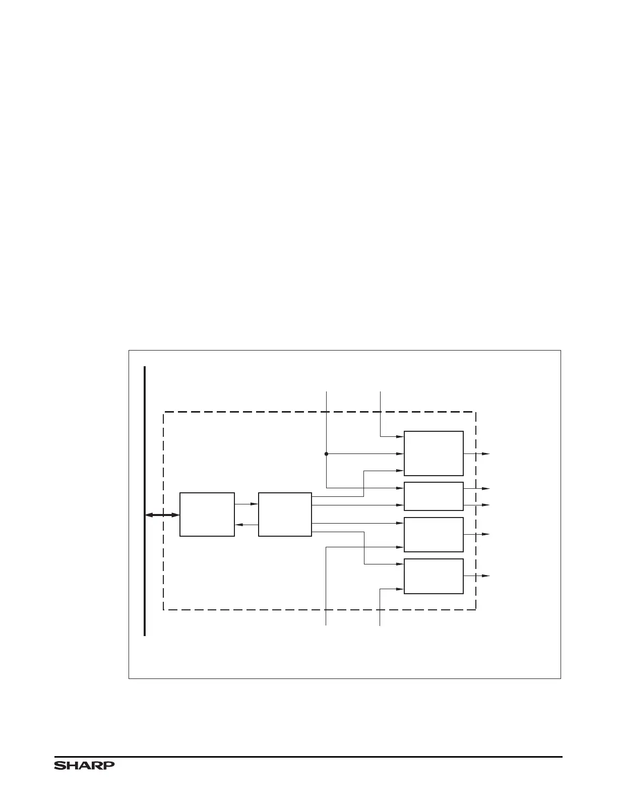
Figure 3-1 shows the Boot Controller block diagram.
Figure 3-1. Boot Controller Block Diagram
REGISTER
BLOCK
nCS1
OVERRIDE
AHB
CONTROL
TO nCS1
TO BOOT ROM
BOOT
CONTROL
NAND FLASH:
nFRE, nFWE
FROM AHB
DECODER
PC[7:4] EXTERNAL
ADDRESS and
CONTROL
AHB
CONTROL
EXTERNAL
PERIPHERAL
INTERFACE
CONTROL
BOOT
CONTROL
NAND
FLASH
CONTROL
AMBA
APB
INTERFACE
LH79525-6
ADVANCED
PERIPHERAL
BUS (APB)