LH79524/LH79525 User’s Guide Analog-to-Digital Converter/Brownout Detector
Version 1.0 2-23
2.2.2.11 Idle High Word Register (IHWCTRL)
IHWCTRL is the high word of the Idle Register. The active bits used in this register are
Read/Write.
This register specifies the idle setting time and the inputs connected to the ADC during the
Idle state. This register is used with the ILWCTRL Register (see Section 2.2.2.12).
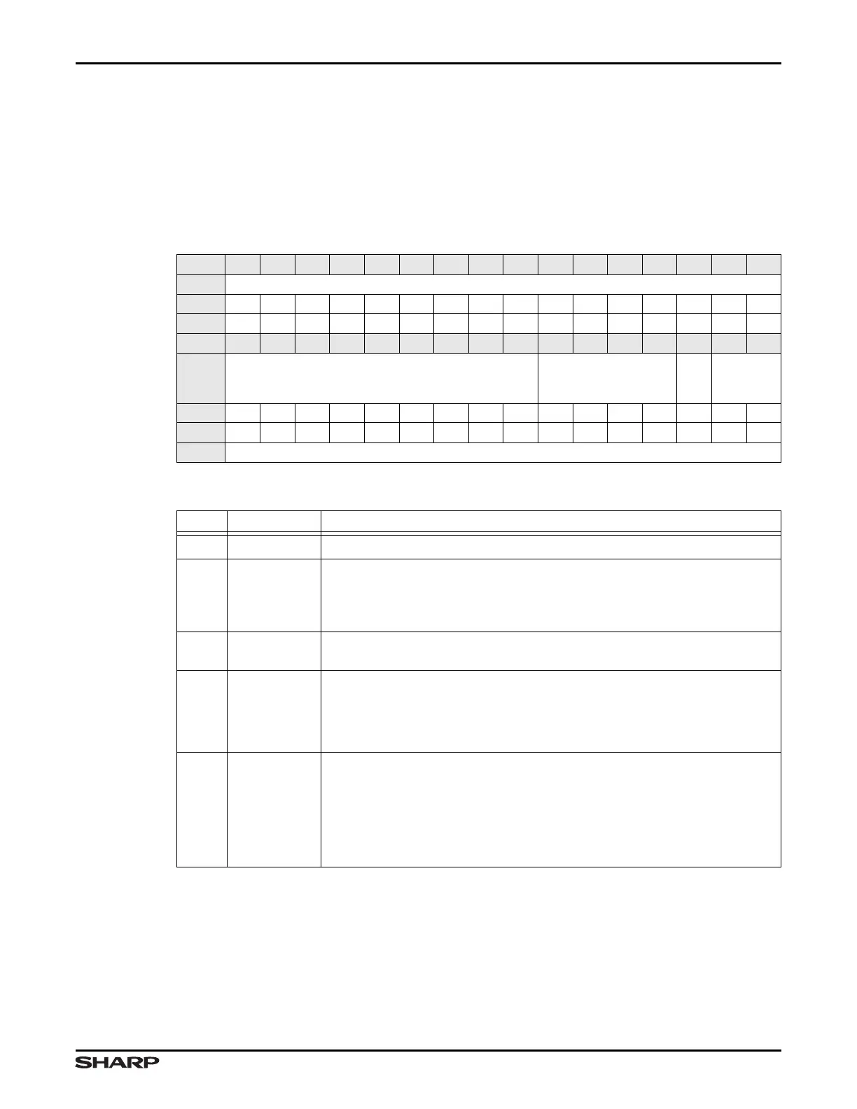
Table 2-23. IHWCTRL Register
BIT 31 30 29 28 27 26 25 24 23 22 21 20 19 18 17 16
FIELD ///
RESET 0000000000000000
RW RO RO RO RO RO RO RO RO RO RO RO RO RO RO RO RO
BIT 15 14 13 12 11 10 9 8 7 6 5 4 3 2 1 0
FIELD SETTIME_ID INP_ID
INM_ID
REFP_ID
RESET 0000000000000000
RW RW RW RW RW RW RW RW RW RW RW RW RW RW RW RW RW
ADDR 0xFFFC3000 + 0xA4
Table 2-24. IHWCTRL Fields
BIT NAME DESCRIPTION
31:16
/// Reserved Reading returns 0. Write the reset value.
15:7 SETTIME_ID
Idle Settling Time Specifies the delay, in ADC clock cycles, from when
the state machine enters the Idle state to when the Pen Interrupt signal
can be activated. Prevents spurious trigger of Pen Interrupt while analog
signals set up by the IDLE Register are settling.
6:3 INP_ID
Idle In+ Mux Specifies the connection to the positive input of the ADC
during Idle Mode. See Table 2-4.
2 INM_ID
Idle In- Mux Specifies the connection to the negative input of the ADC
during Idle Mode.
1 = GND
0 = Ref-
1:0 REFP_ID
Idle Ref+ Mux Specifies the connection to the positive reference of the
ADC during Idle Mode.
00 = VREF+
01 = AN0/UL/X+
10 = AN2/LL/Y+
11 = AN8