Synchronous Serial Port LH79524/LH79525 User’s Guide
14-12 Version 1.0
14.2.2.2 Control Register 1 (CTRL1)
CTRL1 is the Control Register 1. CTRL1 contains four bit fields that control various SSP
functions.
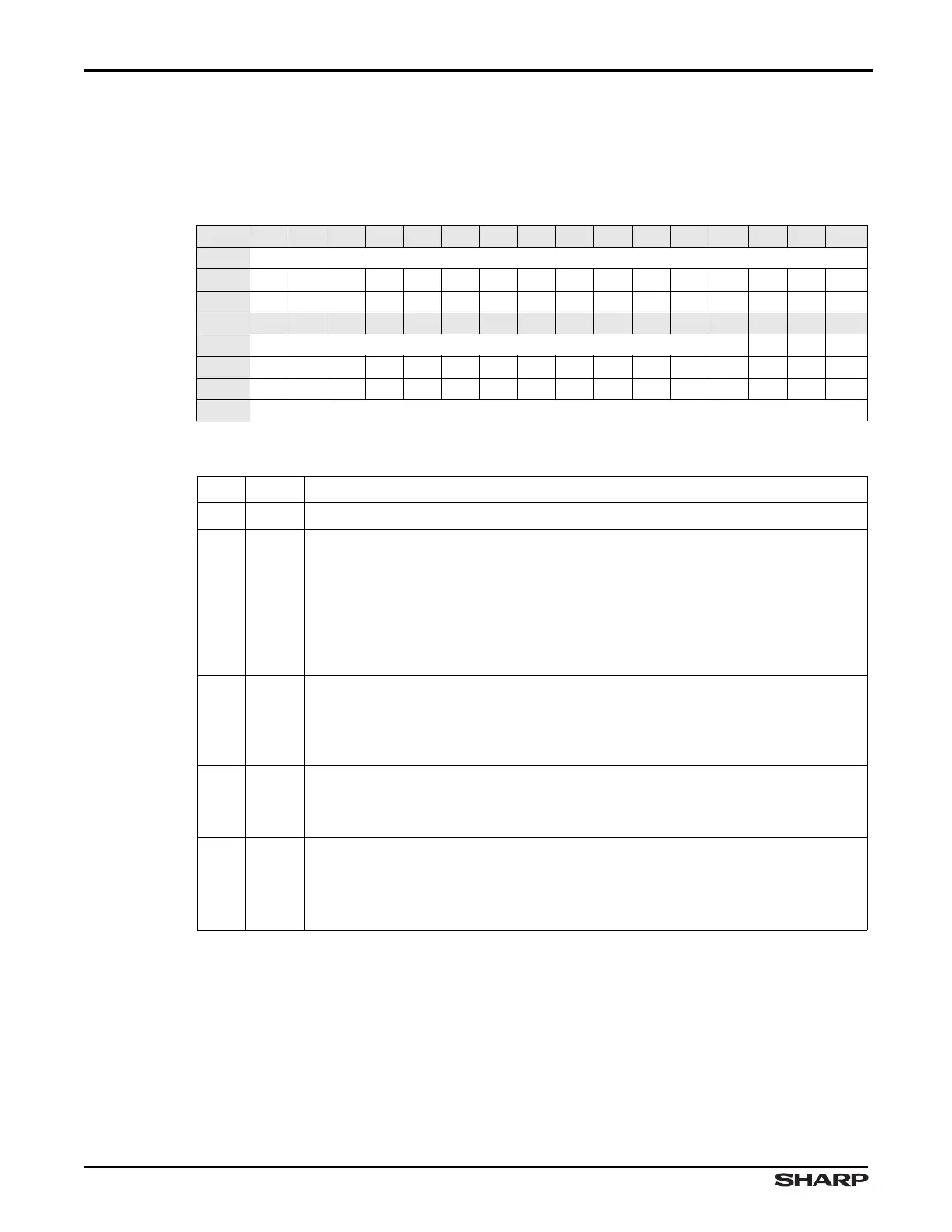
Table 14-5. CTRL1 Register
BIT 31 30 29 28 27 26 25 24 23 22 21 20 19 18 17 16
FIELD ///
RESET 000000000000000 0
RW RO RO RO RO RO RO RO RO RO RO RO RO RO RO RO RO
BIT 15 14 13 12 11 10 9 8 7 6 5 4 3 2 1 0
FIELD /// SOD MS SSE LBM
RESET 000000000000000 0
RW RO RO RO RO RO RO RO RO RO RO RO RO RW RW RW RW
ADDR 0xFFFC6000 + 0x004
Table 14-6. CTRL1 Fields
BITS NAME DESCRIPTION
31:4 /// Reserved Reading returns 0. Write the reset value.
3SOD
Slave Mode Output Disable This bit is relevant only in the slave mode
(MS = 1). In multiple-slave systems, it is possible for an SSP master to broadcast a
message to all slaves in the system while ensuring that only one slave drives data
onto its serial output line. In such systems the RX lines from multiple slaves could
be tied together. To operate in such systems, the SOD bit can be programmed to 1.
1 = SSP must not drive the SSPTX output in slave mode
0 = SSP can drive the SSPTX output in slave mode
2MS
Master or Slave Mode Select This bit can only be modified when the SSP is
disabled, SSE = 0.
1 = device configured as slave
0 = device configured as master
1SSE
Synchronous Serial Port Enable This bit enables and disables the SSP.
1 = SSP operation is enabled
0 = SSP operation is disabled
0LBM
Loopback Mode Program this bit to enable or disable Loopback mode:
1 = Enables Loopback mode, internally connecting the Transmit serial shifter out-
put to the Receive serial shifter input
0 = Enables normal serial port operation, disabling Loopback mode