LH79524/LH79525 User’s Guide Timers
Version 1.0 15-7
15.2.2 Register Descriptions
15.2.2.1 Timer 0 Control Register (CTRL0)
This register allows programming the clock divisor, as well as starting/stopping, and clear-
ing the timer count value.
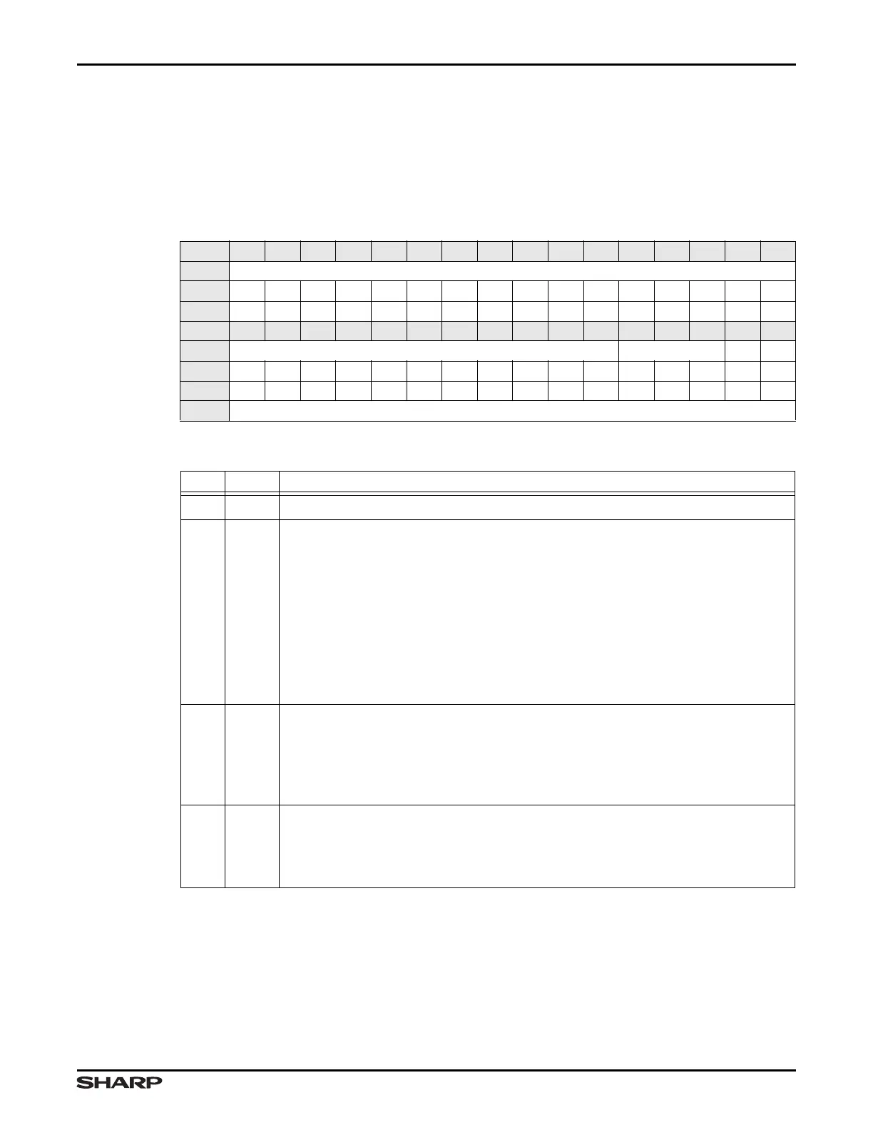
Table 15-4. CTRL0 Register
BIT 31 30 29 28 27 26 25 24 23 22 21 20 19 18 17 16
FIELD ///
RESET 0000000000000000
RW RO RO RO RO RO RO RO RO RO RO RO RO RO RO RO RO
BIT 15 14 13 12 11 10 9 8 7 6 5 4 3 2 1 0
FIELD /// SEL CS CCL
RESET 0000000000000000
RW RO RO RO RO RO RO RO RO RO RO RO RW RW RW RW RW
ADDR 0xFFFC4000 + 0x00
Table 15-5. CTRL0 Register Definitions
BITS NAME DESCRIPTION
31:5 ///
Reserved Reading this field returns 0. Write the reset value.
4:2 SEL
Timer 0 Clock Select Specifies the timer clock divisor. The timer must be
stopped (with the CS bit) before programming the divisor.
000 = HCLK/2
001 = HCLK/4
010 = HCLK/8
011 = HCLK/16
100 = HCLK/32
101 = HCLK/64
110 = HCLK/128
111 = CTCLK
1CS
Start/Stop Timer 0 Count Specifies whether Timer 0 count is stopped or start-
ed. This bit must be programmed to 0 before programming the SEL bit. For more
information, see Section 15.1.1.
1 = Starts Timer 0
0 = Stops Timer 0
0CCL
Timer 0 Count Clear Programming a 1 clears the timer count value. This bit
always reads as 0.
1 = Clears CNT0 contents to 0x0000
0 = Ignored; no effect