LH79524/LH79525 User’s Guide Reset, Clock, and Power Controller
Version 1.0 13-19
13.2.2.9 Peripheral Clock Control Register 0 (PCLKCTRL0)
This register controls the RTC, UART0, UART1, and UART2 peripheral clocks. Program-
ming a bit to 1 disables the corresponding peripheral’s clock. These clocks are more fully
described in Table 13-1.
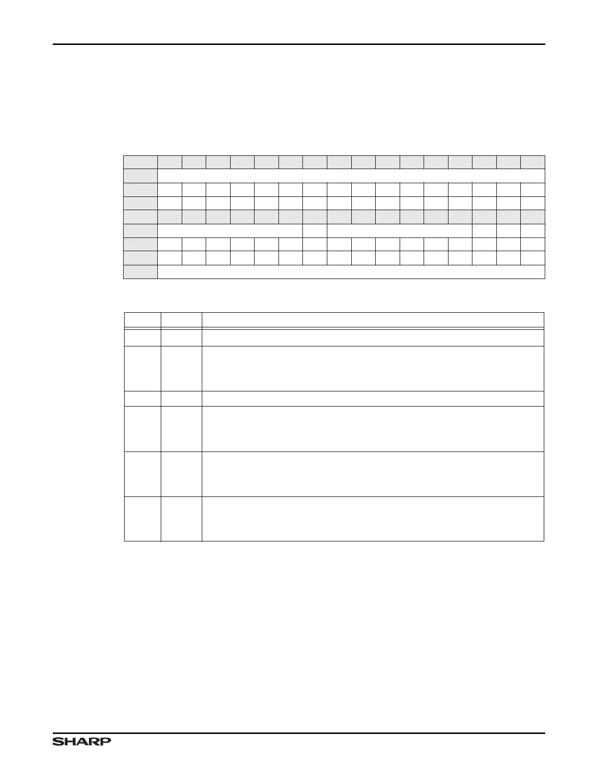
Table 13-22. PCLKCTRL0 Register
BIT 31 30 29 28 27 26 25 24 23 22 21 20 19 18 17 16
FIELD ///
RESET 0000000000000000
RW RO RO RO RO RO RO RO RO RO RO RO RO RO RO RO RO
BIT 15 14 13 12 11 10 9 8 7 6 5 4 3 2 1 0
FIELD /// RTC /// U2 U1 U0
RESET 0000001111111111
RW RO RO RO RO RO RO RW RW RW RW RW RW RW RW RW RW
ADDR 0xFFFE2000 + 0x24
Table 13-23. PCLKCTRL0 Fields
BITS NAME DESCRIPTION
31:10 /// Reserved Reading returns 0. Write the reset value.
9RTC
RTC Clock
1 = Disables the RTC input clock
0 = Enables the RTC input clock
8:3 /// Reserved Reading returns 1. Write the reset value.
2U2
UART2 Clock Enables and disables the internal clock to UART2.
1 = Disables the UART2 clock
0 = Enables the UART2 clock
1U1
UART1 Clock Enables and disables the internal clock to UART1.
1 = Disables the UART1 clock
0 = Enables the UART1 clock
0U0
UART0 Clock Enables and disables the internal clock to UART0.
1 = Disables the UART0 clock
0 = Enables the UART0 clock