LH79524/LH79525 User’s Guide Reset, Clock, and Power Controller
Version 1.0 13-11
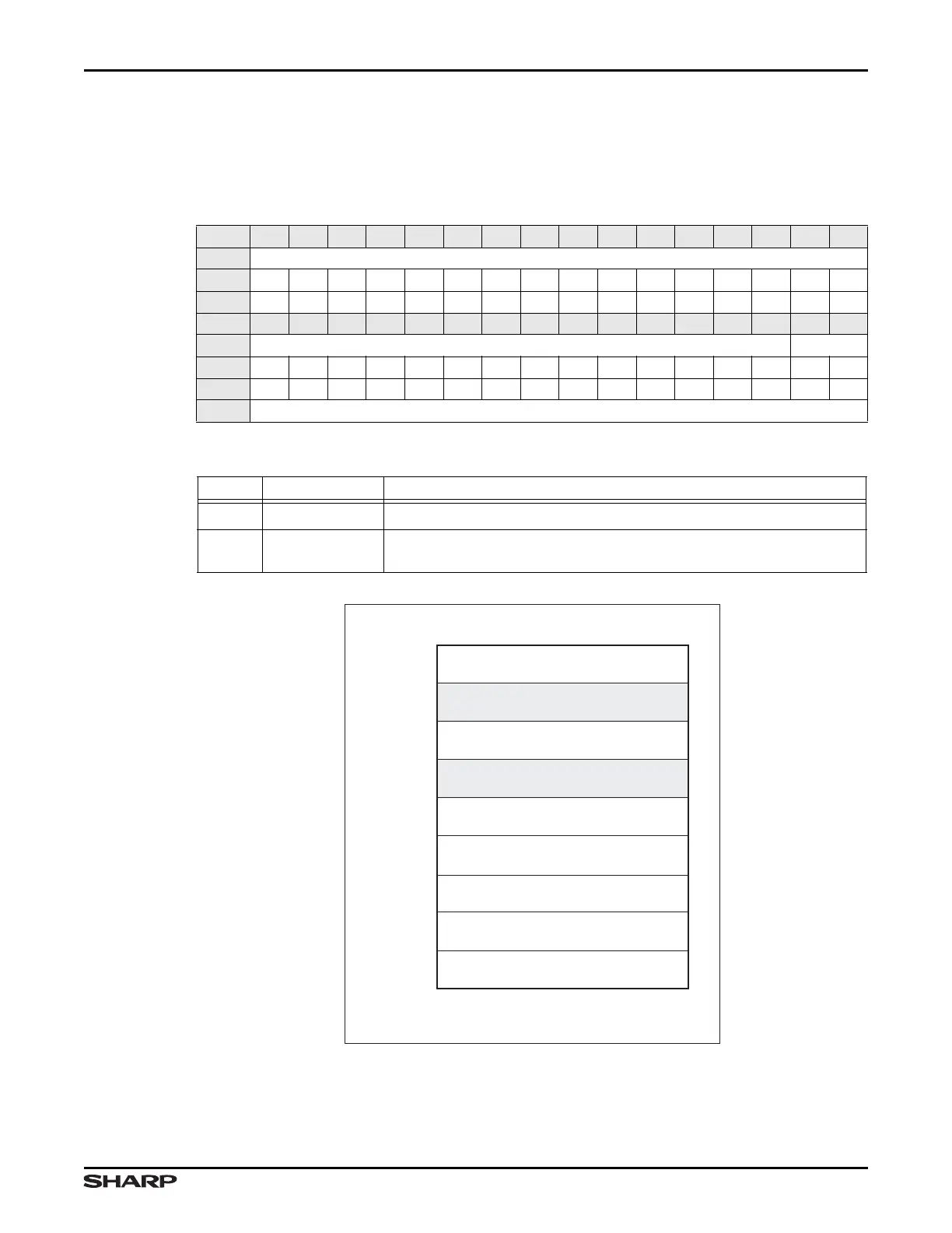
13.2.2.3 Remap Control Register (REMAP)
This REMAP Register provides a remapping feature for the system memory map.
Figure 13-3 through Figure 13-6 show the effects of the REMAP bits.
Table 13-8. REMAP Register
BIT 31 30 29 28 27 26 25 24 23 22 21 20 19 18 17 16
FIELD ///
RESET 0000000000000000
RW RO RO RO RO RO RO RO RO RO RO RO RO RO RO RO RO
BIT 15 14 13 12 11 10 9 8 7 6 5 4 3 2 1 0
FIELD /// REMAP
RESET 0000000000000000
RW RO RO RO RO RO RO RO RO RO RO RO RO RO RO RW RW
ADDR 0xFFFE2000 + 0x08
Table 13-9. REMAP Fields
BITS NAME DESCRIPTION
31:2 /// Reserved Reading returns 0. Write the reset value.
1:0 REMAP
REMAP Remaps external and internal memory, system peripher-
als, and registers, as shown Figure 13-3 through Figure 13-6.
Figure 13-3. Remap = 0b00
LH79525-1
ADVANCED HIGH-PERFORMANCE BUS
PERIPHERALS
ADVANCED PERIPHERAL BUS
PERIPHERALS
RESERVED
EXTERNAL SRAM nCS1
REMAP = 00
EXTERNAL STATIC MEMORY
EXTERNAL SDRAM
16KB INTERNAL SRAM
BOOT ROM
RESERVED
0xFFFFFFFF
0xFFFF1000
0xFFFF0000
0xFFFC0000
0xA0000000
0x80000000
0x60000000
0x40000000
0x20000000
0x00000000