External Memory Controller LH79524/LH79525 User’s Guide
7-30 Version 1.0
7.5.2 Register Definitions
7.5.2.1 Control Register (CONTROL)
The CONTROL Register controls the memory controller operation. The control bits can be
altered during normal operation.
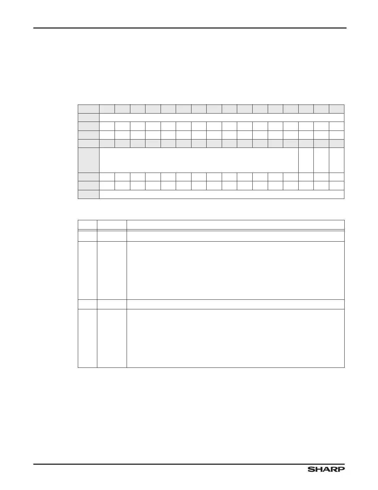
Table 7-11. CONTROL Register
BIT 31 30 29 28 27 26 25 24 23 22 21 20 19 18 17 16
FIELD ///
RESET 0000000000000000
TYPE RO RO RO RO RO RO RO RO RO RO RO RO RO RO RO RO
BIT 15 14 13 12 11 10 9 8 7 6 5 4 3 2 1 0
FIELD ///
MODE
///
ENABLE
RESET 0000000000000001
TYPE RO RO RO RO RO RO RO RO RO RO RO RO RO RW RW RW
ADDR 0xFFFF1000 + 0x000
Table 7-12. CONTROL Fields
BITS NAME FUNCTION
31:3 /// Reserved Reading returns 0. Write the reset value.
2MODE
Mode select Entering low-power mode reduces memory controller power
consumption. Dynamic memory is refreshed as necessary. The memory con-
troller returns to normal functional mode by clearing the low-power mode bit.
External memory cannot be accessed in low-power state. If a memory access
is performed, an error response is generated.
1 = Low-power Mode
0 = Normal Mode
1///Reserved Reading returns 0. Write the reset value.
0 ENABLE
Enable the EMC Disabling the External Memory Controller reduces power
consumption. When the memory controller is disabled the memory is not re-
freshed. The memory controller is enabled by setting the enable bit. The exter-
nal memory cannot be accessed in disabled state. If a memory access is
performed, an error response is generated.
1 = Enabled
0 = Disabled