LH79524/LH79525 User’s Guide Timers
Version 1.0 15-5
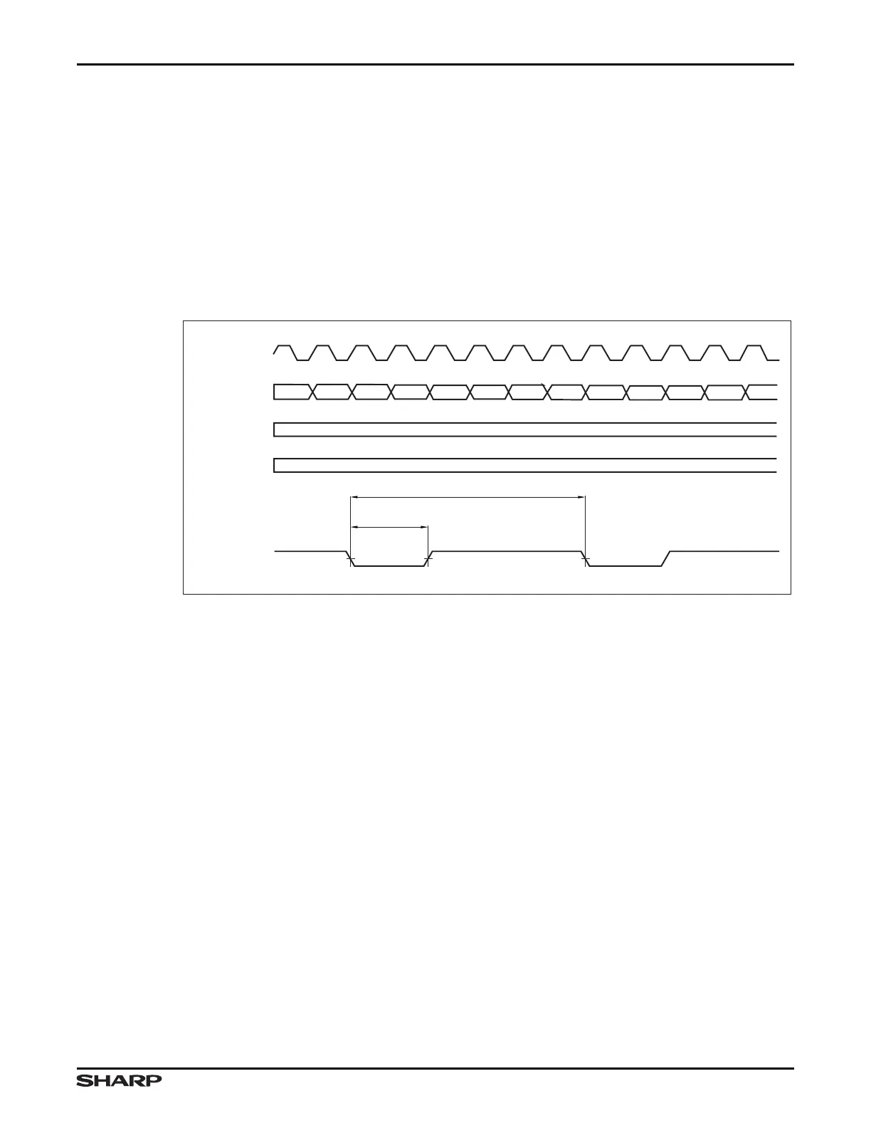
Figure 15-5 shows an example of PWM output signal timing. To implement the timing
shown in this Figure, the following values are programmed into the registers.
• TxCMP1 = 0x0005 (Period of 6)
• TxCMP0 = 0x0001 (Duty Cycle of 2; ‘OFF TIME’ in Figure 15-5)
Timer 0 settings:
• CMP_CAP_CTRL:PWM = 1 (Enable PWM mode)
• CMP_CAP_CTRL:TC = 1 (Counter Clear Mode)
• CMP_CAP_CTRL:CMP1 = 01 (Active HIGH PWM polarity)
• CMP_CAP_CTRL:CMP0 = 10 (Active HIGH PWM polarity)
15.1.3.1 Timer Interrupts
The timer interrupts are:
• Timer 0 Combined Interrupt — a combined interrupt formed by the logical OR of the two
compare, five capture, and one overflow interrupts in Timer 0.
• Timer 1 Combined Interrupt — a combined interrupt formed by the logical OR of the two
compare, two capture, and one overflow interrupts in Timer 1.
• Timer 2 Combined Interrupt — a combined interrupt formed by the logical OR of the two
compare, two capture, and one overflow interrupts in Timer 2.
If an individual interrupt is enabled and the corresponding interrupt condition (compare, cap-
ture, or overflow) occurs, a combined interrupt also occurs. Once the interrupt condition occurs,
the combined Interrupt Output signal is asserted active to 1. It remains active until all compare,
capture, and overflow interrupts are cleared in the appropriate Status Register, or disabled.
Interrupts can be individually enabled or disabled in the respective timer’s INTENx register.
The STATUSx registers allow software to read the status of each interrupt. Software can
logically AND the STATUSx with the INTENx register to ascertain which enabled interrupts
are asserted to the VIC.
Figure 15-5. PWM Output Signal Timing
CNT
REGISTER
CMP1
REGISTER
CMP0
REGISTER
PWM OUTPUT
(CTCMPxA)
INTERNAL
COUNT CLOCK
0x00040x0003 0x0005 0x0000 0x0001
0x0005
PERIOD = 6
OFF
TIME
0x0001
0x0002 0x0003 0x0004 0x0005 0x0000 0x0001 0x0002 0x000
LH79525-36