LH79524/LH79525 User’s Guide Universal Serial Bus Device
Version 1.0 17-13
17.2.2.4 Interrupt Register for OUT Endpoint 1 and 2 (OIR)
The OUT Interrupt register (OIR) acts as an interrupt status register for the OUT endpoint EP1
and EP2. Upon interrupt, software should read each of the three interrupt registers (IIR, OIR,
and UIR), which clears the interrupt bit. The UIR must be the last register read and cleared.
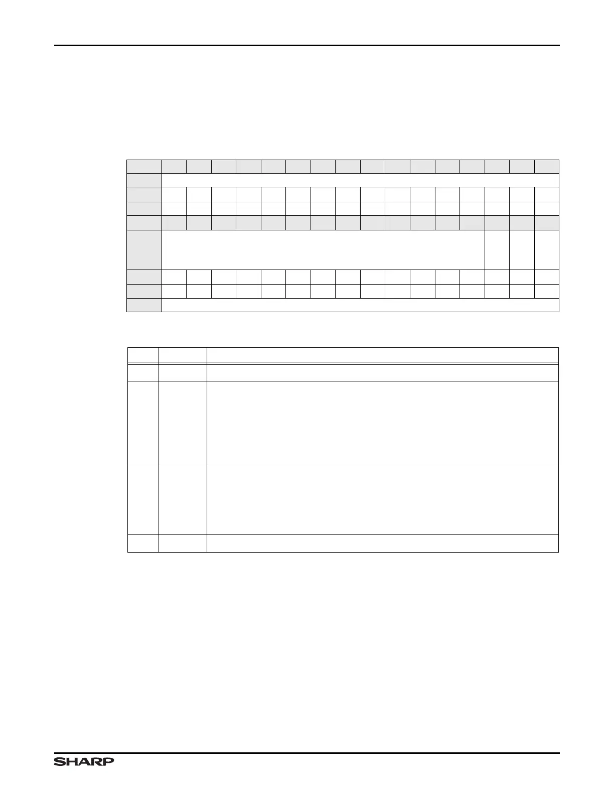
Table 17-10. OIR Register
BIT 31 30 29 28 27 26 25 24 23 22 21 20 19 18 17 16
FIELD ///
RESET 0000000000000000
RW RO RO RO RO RO RO RO RO RO RO RO RO RO RO RO RO
BIT 15 14 13 12 11 10 9 8 7 6 5 4 3 2 1 0
FIELD ///
EP2OUT
EP1OUT
///
RESET 0000000000000000
TYPE RO RO RO RO RO RO RO RO RO RO RO RO RO RO RO RO
ADDR 0xFFFF5000 + 0x010
Table 17-11. OIR Fields
BITS NAME FUNCTION
31:3
/// Reserved Reading returns 0. Write the reset value.
2 EP2OUT
EP2 Out Interrupt This interrupt is generated for Isochronous OUT trans-
fers. The USB block programs this bit to 1 when: OUT_PKT_RDY and
SENT_STALL are set to 1 by the USB Host. Software clears this interrupt by
reading this register.
1 = Isochronous OUT transfer is ready
0 = Interrupt cleared or the above conditions are not met
1 EP1OUT
EP1 Out Interrupt This interrupt is generated for BULK OUT transfers. The
USB block programs this bit to 1 when: OUT_PKT_RDY and SENT_STALL are
set to 1 by the USB Host. Software clears this interrupt by reading this register.
1 = BULK OUT transfer is ready
0 = Interrupt cleared or the above conditions are not met
0
/// Reserved Reading returns 0. Write the reset value.