LH79524/LH79525 User’s Guide I
2
C Module
Version 1.0 9-9
9.2.2.3 I
2
C Upper Slave Address Register (ICUSAR)
Software programs the ICUSAR register with the upper 2 address bits in 10-bit addressing
mode, plus the read/write data direction (SRW) bit. This register is not used in Master mode.
9.2.2.4 I
2
C Data Register (ICDATA)
The ICDATA register holds the received data or the data to be transmitted.
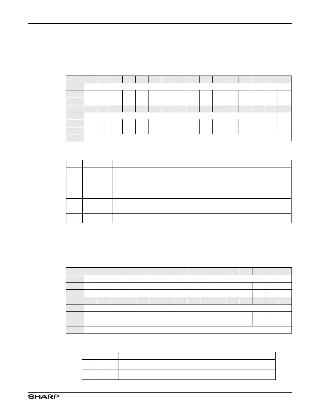
Table 9-8. ICUSAR Register
BIT 31 30 29 28 27 26 25 24 23 22 21 20 19 18 17 16
FIELD ///
RESET 000000000000000 0
TYPE RO RO RO RO RO RO RO RO RO RO RO RO RO RO RO RO
BIT 15 14 13 12 11 10 9 8 7 6 5 4 3 2 1 0
FIELD /// UPPERAD SLAD89 ///
RESET 000000000000000 0
TYPE RO RO RO RO RO RO RO RO RW RW RW RW RW RW RW RW
ADDR 0xFFFC5000 + 0x08
Table 9-9. ICUSAR Fields
BITS NAME DESCRIPTION
31:8 /// Reserved Reading returns 0. Write the reset value.
7:3 UPPERAD
Upper Address This field is only used for 10-bit mode. When using 10-bit
mode, this field must be programmed to 0b11110. When using 7-bit mode,
this field must be programmed to 0b00000, which is the reset value.
2:1 SLAD89
Slave Address Bits [9:8] This field contains the upper 2 bits of the 10-bit
slave address. This field is not used in 7-bit addressing mode.
0
/// Reserved Reading returns 0. Write the reset value.
Table 9-10. ICDATA Register
BIT 31 30 29 28 27 26 25 24 23 22 21 20 19 18 17 16
FIELD ///
RESET 0000000000000000
TYPE RO RO RO RO RO RO RO RO RO RO RO RO RO RO RO RO
BIT 15 14 13 12 11 10 9 8 7 6 5 4 3 2 1 0
FIELD /// DAT
RESET 0000000000000000
TYPE RO RO RO RO RO RO RO RO RW RW RW RW RW RW RW RW
ADDR 0xFFFC5000 + 0x0C
Table 9-11. ICDATA Fields
BITS NAME DESCRIPTION
31:8 /// Reserved Reading returns 0. Write the reset value.
7:0 DAT
I
2
C Data This field contains the transmitted or received I
2
C data.