LH79524/LH79525 User’s Guide Preface
Version 1.0 xxxix
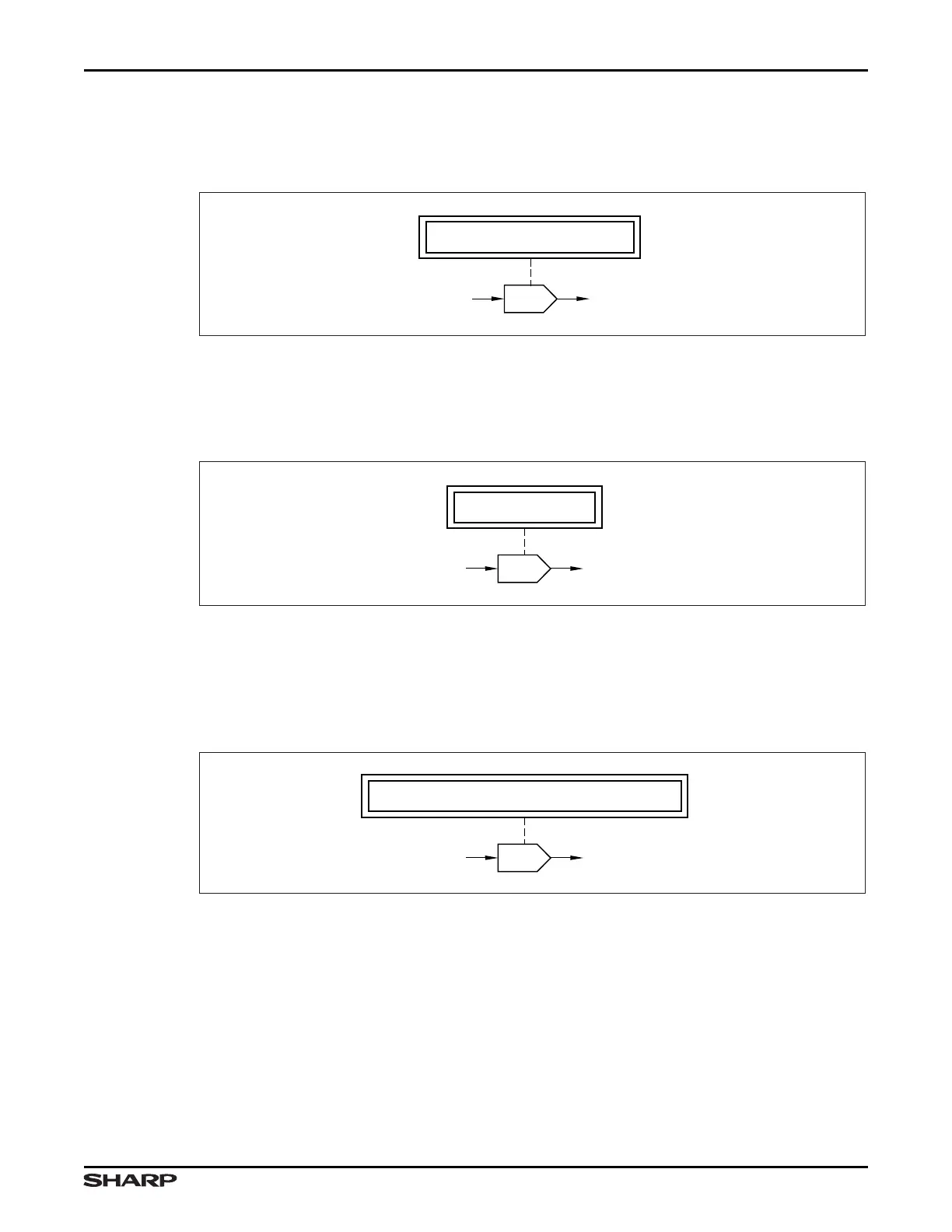
Block diagrams can include symbols representing Registers and the bit fields within them.
Figure 2 shows that the BITFIELDNAME bit field in the REGISTERNAME register enables
or disables the signal named OUTPUT.
Figure 3 is similar to Figure 2 except that Figure 3 references multiple (different)
BITFIELDS in the REGISTERNAME register.
Not all bit fields are named. If a bit field has no name, the Register is shown with numbers
indicating the appropriate bit positions, with the least significant bit on the right, as in
Figure 4. This bit ordering matches that of the Register tables, shown in Table 1.
Figure 2. Register with Bit-Field Named
LH7A404-9
OUTPUT
REGISTERNAME:BITFIELDNAME
INPUT
f ( )
Figure 3. Register with Multiple Bit-Fields Named
REGISTERNAME: 15:3
LH7A404-93
OUTPUTINPUT
f ( )
Figure 4. Register with Bit-Field Numbered
REGISTERNAME: [BITFIELDNAME, BITFIELDNAME]
7A404-94
OUTPUTINPUT
f ( )