Analog-to-Digital Converter/Brownout Detector LH79524/LH79525 User’s Guide
2-16 Version 1.0
2.2.2.5 Power Configuration Register (PC)
In this register, the clock divider bits are programmed to set the system clock frequency for
analog operation. Program bits [3:0] to the number of conversions necessary, depending
on the conversion. Bit [4] can be used as an enable for external I/O pads. If this bit is set
to 1, the Battery Control Logic Pin (BATCNTL) will be a valid output. If an external battery
measurement circuit is not used, this bit should be set to 0.
NOTE: Allow two A2DCLK cycles between successive write cycles to this register. Otherwise, ADC behavior
can become erratic.
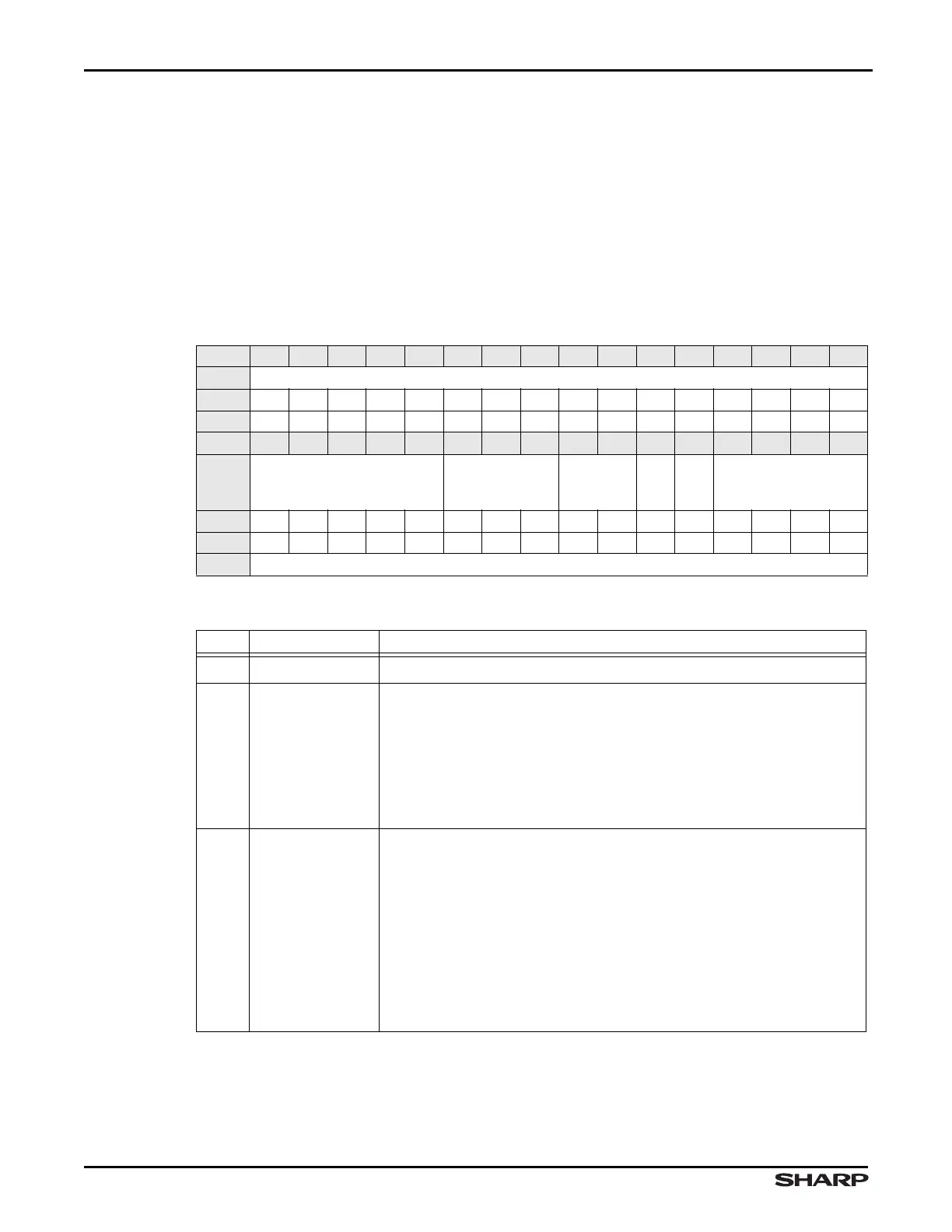
Table 2-11. PC Register
BIT 31 30 29 28 27 26 25 24 23 22 21 20 19 18 17 16
FIELD ///
RESET 0000000000000000
RW RO RO RO RO RO RO RO RO RO RO RO RO RO RO RO RO
BIT 15 14 13 12 11 10 9 8 7 6 5 4 3 2 1 0
FIELD BATLOC CLKSEL PWM
REFEN
BATEN
NOC
RESET 0000000000000000
RW RO RW RW RW RW RW RW RW RW RW RW RW RW RW RW RW
ADDR 0xFFFC3000 + 0x10
Table 2-12. PC Fields
BIT NAME DESCRIPTION
31:15
/// Reserved Reading returns 0. Write the reset value.
14:11 BATLOC
Battery Measurement Location Program this field with the
Channel number corresponding to the location programmed into the
HW:INP field for battery measurement. When PC:BATLOC = HW:INP,
the output pin BATCNTL goes HIGH. At all other times, the BATCNTL
pin is LOW.
To disable toggling the BATCNTL pin, program these bits to a value
that will never appear in HW:INP, for example 0b1111.
10:8 CLKSEL
Clock Select If the nominal value is used, the only valid settings are
011, 100, 101, and 110.
000 = Clock oscillator (nominally 10 to 20 MHz)
001 = Clock oscillator /2
010 = Clock oscillator /4
011 = Clock oscillator /8
100 = Clock oscillator /16
101 = Clock oscillator /32
110 = Clock oscillator /64
111 = Clock oscillator /128