Analog-to-Digital Converter/Brownout Detector LH79524/LH79525 User’s Guide
2-24 Version 1.0
2.2.2.12 Idle Low Word Register (ILWCTRL)
ILWCTRL is the low word of the Idle Register. The active bits used in this register are
Read/Write.
This register specifies the inputs connected to the ADC during the Idle state. This register
is used with the IHWCTRL Register (see Section 2.2.2.11).
IMPORTANT: Bits 9-11 must always be written as 0b000. Writing a 1 to any of these three bits can cause
unpredictable results.
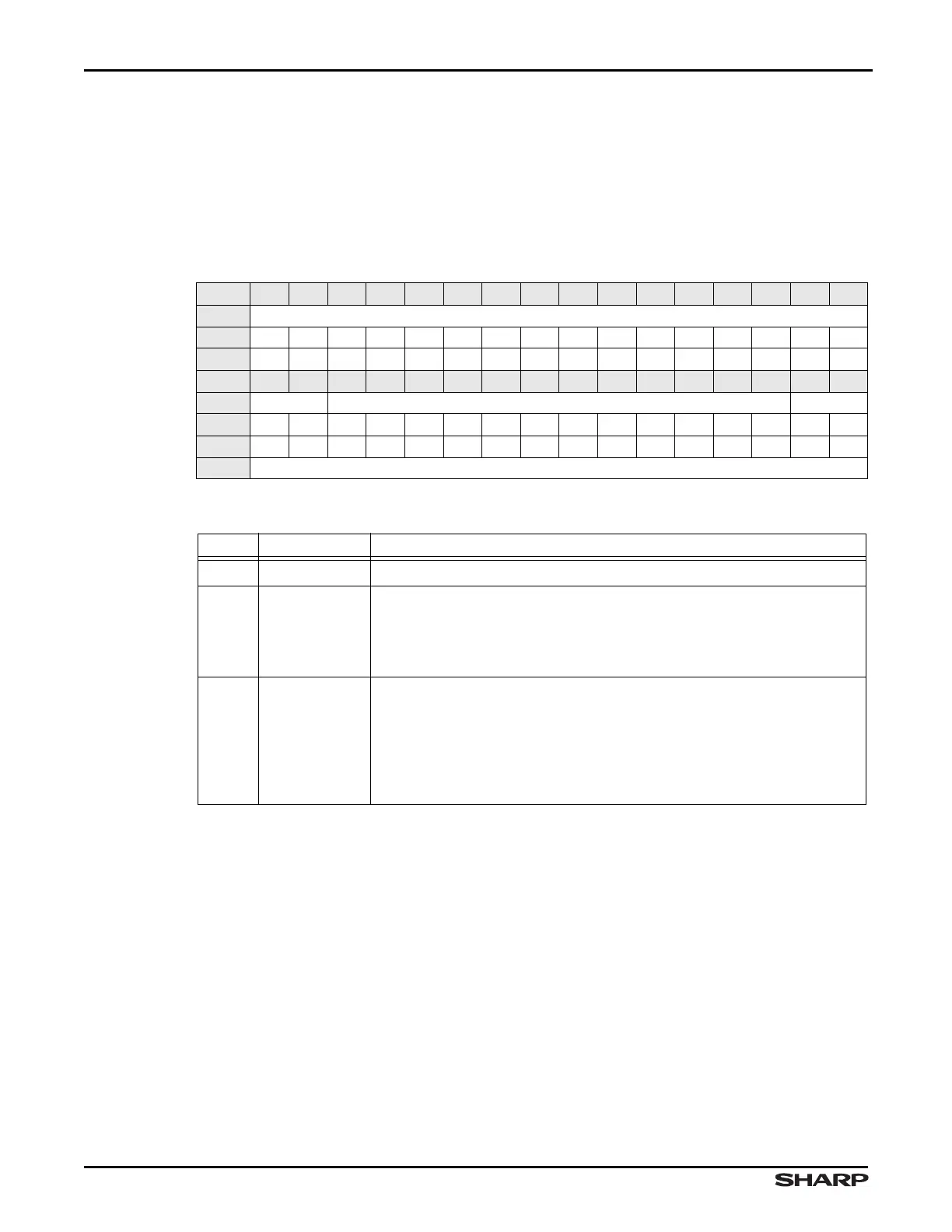
Table 2-25. ILWCTRL Register
BIT 31 30 29 28 27 26 25 24 23 22 21 20 19 18 17 16
FIELD ///
RESET 0000000000000000
RW RO RO RO RO RO RO RO RO RO RO RO RO RO RO RO RO
BIT 15 14 13 12 11 10 9 8 7 6 5 4 3 2 1 0
FIELD /// BIASCON_ID REFM_ID
RESET 0000000000000000
RW RO RO RW RW RW RW RW RW RW RW RW RW RW RW RW RW
ADDR 0xFFFC3000 + 0xA8
Table 2-26. ILWCTRL Fields
BIT NAME DESCRIPTION
31:14 /// Reserved Reading returns 0. Write the reset value.
13:2 BIASCON_ID
Idle Bias Control These bits turn the FETs on and off, as shown in
Figure 2-2. The bit number corresponds to the FET number in the figure.
1 = FET on
0 = FET off
1:0 REFM_ID
Idle Ref- Mux Specifies the connection to the negative reference of
the ADC during Idle Mode.
00 = VREF-
01 = AN1 (UR/X-)
10 = AN3 (LR/Y-)
11 = AN9