Reset, Clock, and Power Controller LH79524/LH79525 User’s Guide
13-2 Version 1.0
13.1 Theory of Operation
The RCPC allows users to control system reset, clocks, power management, and external
interrupt conditioning via the AMBA APB interface. This control includes:
• Enabling and disabling various clocks
• Managing power-down sequencing
• Selecting the sources for various clocks, and any predivision.
The RCPC ensures an orderly start-up until the System Clock crystal oscillator stabilizes
and the Phase Lock Loop (System PLL) acquires lock. In addition, if users want to change
the System PLL or System Clock frequency during normal operation, the RCPC ensures
a seamless transition between the old and new frequencies. The same protection is not
available, however, when changing the frequency of individual peripheral clocks; as
a result, the peripheral must be disabled before changing frequency.
The RCPC also manages five Power Modes:
•Active
• Standby
•Sleep
• Stop1
• Stop2.
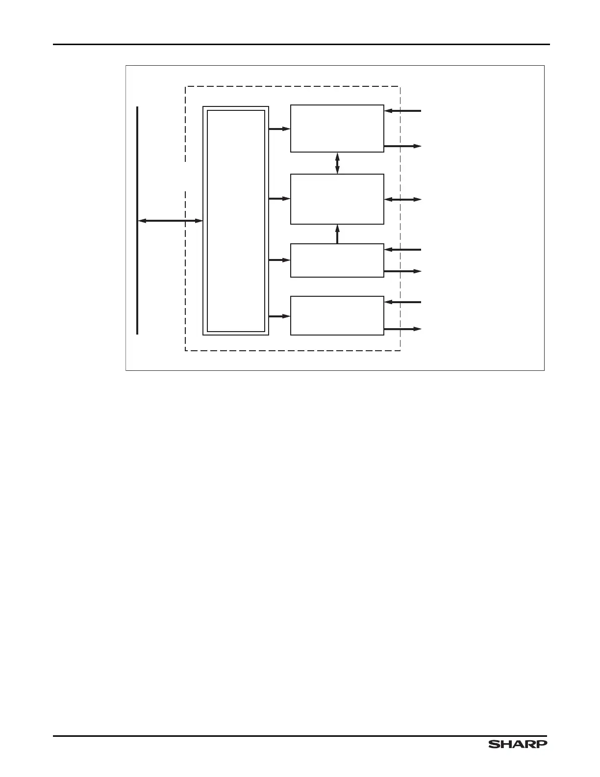
Figure 13-1. RCPC Block Diagram
LH79525-6
RCPC
REGISTERS
SYSTEM CLOCK OSCILLATOR
32.768 kHz OSCILLATOR
PLL CLOCK
EXTERNAL RESET/WDT
RESET INPUTS
GLOBAL/RTC/EXTERNAL
RESET OUTPUTS
EXT ASYNCHRONOUS
INTERRUPT INPUTS
CONDITIONED EXTERNAL
INTERRUPTS TO VECTORED
INTERRUPT CONTROLLER
SYSTEM CLOCK
CPU CLOCK
ON-CHIP PERIPHERAL
CLOCKS
AHB CLOCK
AND PLL INTERFACE
VECTORED INTERRUPT
CONTROLLER FIQ AND
IRQ OUTPUTS
CLOCK CONTROL
BLOCK
RESET CONTROL
BLOCK
EXTERNAL
INTERRUPT CONTROL
BLOCK
POWER DOWN
MODE/FREQUENCY
CHANGE
CONTROL BLOCK
ADVANCED
PERIPHERAL
BUS (APB)