LH79524/LH79525 User’s Guide Color Liquid Crystal Display Controller
Version 1.0 4-33
4.5.3.9 Masked Interrupt Status Register (INTERRUPT)
The INTERRUPT Register is a Read Only register. It is a bit-by-bit logical AND of the
Raw Interrupt Status Register (see Section 4.5.3.8) and the INTREN Register (see
Section 4.5.3.6). Interrupt lines correspond to each interrupt. A logical OR of all interrupts
is provided to the Vectored Interrupt Controller.
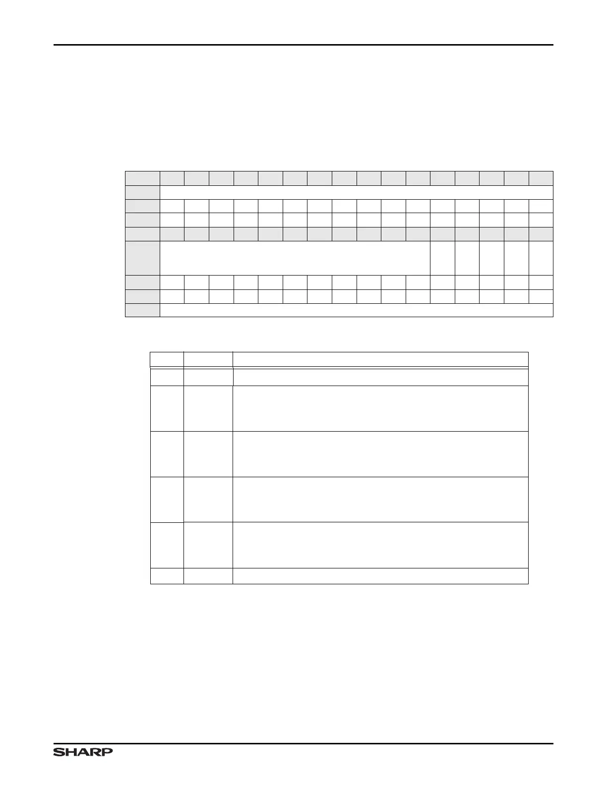
Table 4-30. INTERRUPT Register
BIT 31 30 29 28 27 26 25 24 23 22 21 20 19 18 17 16
FIELD ///
RESET 0000000000000000
RW RO RO RO RO RO RO RO RO RO RO RO RO RO RO RO RO
BIT 15 14 13 12 11 10 9 8 7 6 5 4 3 2 1 0
FIELD ///
MBEIM
VCIM
BUIM
FUIM
///
RESET 0000000000000000
RW RO RO RO RO RO RO RO RO RO RO RO RO RO RO RO RO
ADDR 0xFFFF4000 + 0x24
Table 4-31. INTERRUPT Fields
BIT NAME DESCRIPTION
31:5 /// Reserved Reading returns 0. Write the reset value.
4 MBEIM
Masked AHB Master Error Interrupt
1 = Interrupt asserted and enabled
0 = No interrupt
3VCIM
Masked Vertical Compare Interrupt
1 = Interrupt asserted and enabled
0 = No interrupt
2BUIM
Masked LCD Next Base Address Update Interrupt
1 = Interrupt asserted and enabled
0 = No interrupt
1FUIM
Masked FIFO Underflow Interrupt
1 = Interrupt asserted and enabled
0 = No interrupt
0 /// Reserved Reading returns 0. Write the reset value.