LH79524/LH79525 User’s Guide I
2
C Module
Version 1.0 9-11
9.2.2.7 I
2
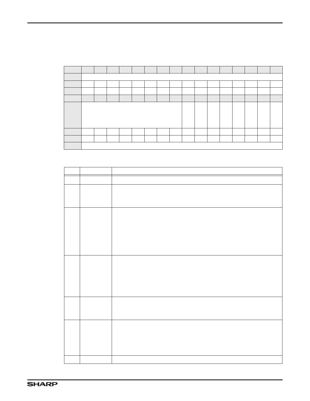
C Status Register (ICSTAT)
The ICSTAT register provides status regarding the state of the module.
Table 9-16. ICSTAT Register
BIT 31 30 29 28 27 26 25 24 23 22 21 20 19 18 17 16
FIELD ///
RESET 0000000000000000
TYPE RO RO RO RO RO RO RO RO RO RO RO RO RO RO RO RO
BIT 15 14 13 12 11 10 9 8 7 6 5 4 3 2 1 0
FIELD ///
SLAVEAD
RXABORT
TXABORT
IDLE
10BITADDR
///
FULL
INTR
RESET 0000000000010000
TYPE RO RO RO RO RO RO RO RO RO RO RO RO RO RO RO RO
ADDR 0xFFFC5000 + 0x1C
Table 9-17. ICSTAT Fields
BITS NAME DESCRIPTION
31:8 /// Reserved Reading returns 0. Write the reset value.
7 SLAVEAD
Slave Address
1 = Last byte received on the I
2
C bus was a Slave address byte
0 = Last byte received was not a Slave address byte
6 RXABORT
Receive Abort This bit indicates a Receive fault.
1 = (Slave Mode) The I
2
C Module is in 10-bit Slave mode and the upper
address bits matched but the lower address bits did not.
1 = (Master Mode) The upper and lower address bits match but a restart
was issued by the Master in Master-receive mode, and the repeated
upper address does not match.
0 = No Receive Abort
5 TXABORT
Transmit Abort This bit indicates a Transmit fault. This bit remains 1 until
the ICSTAT Register is read by software.
1 = I
2
C Module is operating in the Master-transmitter mode and a Slave
device does not respond with an ACK signal after receiving a byte of
data, or arbitration was lost.
0 = No Transmit Abort
4IDLE
Idle Indicates that no messages are currently being processed.
1 = I
2
C Module is not processing any messages
0 = I
2
C Module is actively processing messages
3 10BITADDR
10-bit Address This status bit denotes that a 10-bit address was detected.
This bit remains 1 until automatically cleared when the ICSTAT Register is
read by software.
1 = A 10-bit address is detected
0 = No 10-bit address detected
2///Reserved Reading returns 0. Write the reset value.