I
2
S Converter LH79524/LH79525 User’s Guide
10-14 Version 1.0
10.2.2 Register Descriptions
Note that SSP register bits duplicated in the I
2
S Converter will lag the SSP version of the
bit by one clock.
10.2.2.1 Control Register (CTRL)
This register allows control of various I
2
S Converter functions, including Loopback, clock
inversion, WS control, enabling the converter and selecting its mode.
Notice that some
of the functions apply only to
I
2
S transactions; for SSP transactions, those bits are
not active. Explanation of the ‘WS’ function appears following Table 10-3.
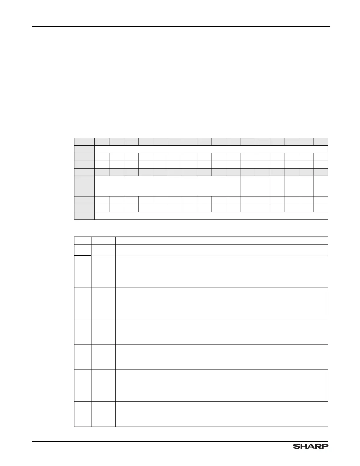
Table 10-2. CTRL Register
BIT 31 30 29 28 27 26 25 24 23 22 21 20 19 18 17 16
FIELD ///
RESET 0000000000000000
RW RO RO RO RO RO RO RO RO RO RO RO RO RO RO RO RO
BIT 15 14 13 12 11 10 9 8 7 6 5 4 3 2 1 0
FIELD ///
LOOP
CLKINV
WSDEL
WSINV
I2SEN
I2SLBM
RESET 0000000000000000
RW RO RO RO RO RO RO RO RO RO RO RW RW RW RW RW RW
ADDR 0xFFFC8000 + 0x000
Table 10-3. CTRL Register Definitions
BITS NAME DESCRIPTION
31:6 /// Reserved Reading returns 0. Write the reset value.
5LOOP
Loopback Mode Applies only to I
2
S Transactions. Note that two frames of 0x0000 will
still be received in master mode.
1 = Transmit and Receive internally connected for Loopback Mode
0 = Normal operation
4CLKINV
Clock Invert Applies only to I
2
S Transactions. Inverts the polarity of the SSPCLK or
I2SCLK, which is output on the PB3SSPCLK/I2SCLK pin.
1 = Invert SSPCLK/I2SCLK
0 = Do not invert SSPCLK/I2SCLK
3 WSDEL
WS Delay Applies only to I
2
S Transactions
1 = WS transitions with MSB (left justified)
0 = WS transitions one clock before MSB (I
2
S justified)
2WSINV
WS Invert Applies only to I
2
S Transactions (see Table 10-6)
1 = Invert the function of WS (first sampled driven/latched will have WS = 1)
0 = No change in function of WS (first sampled driven/latched will have WS = 0)
1 I2SEN
Enable I
2
S Converter When this bit is 0, the registers in the I
2
S data and frame paths
are cleared, and the master and slave clock inputs are gated off.
1 = Enable I
2
S converter, convert between SSP mode and I
2
S formats
0 = Disable I
2
S converter, pass through SSP signals unchanged
0 I2SEL
I
2
S Select
1 = I
2
S functions are selected
0 = SSP functions are selected