I/O Configuration LH79524/LH79525 User’s Guide
11-22 Version 1.0
11.2.2.15 Multiplexing Control 11 Register (MUXCTL11)
The MUXCTL11 Register allows software to configure a number of LH79524/LH79525
pins. Bits marked ‘LH79524 Only’ read as 0 with all writes ‘reserved’ on the LH79525.
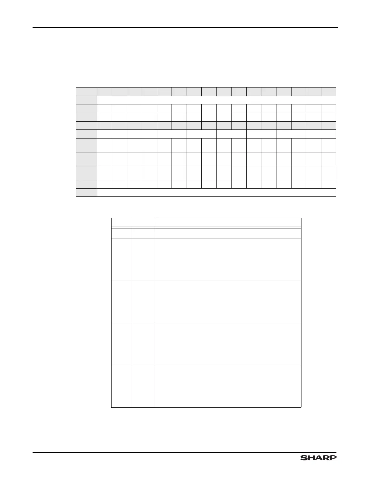
Table 11-30. MUXCTL11 Register
BIT 31 30 29 28 27 26 25 24 23 22 21 20 19 18 17 16
FIELD ///
RESET 0000000000000000
RW RO RO RO RO RO RO RO RO RO RO RO RO RO RO RO RO
BIT 15 14 13 12 11 10 9 8 7 6 5 4 3 2 1 0
FIELD PD4 PK4 PD3 PK3 PD2 PK2 PK1 PD1
RESET
8-Bit
0000000000000000
RESET
16-Bit
0100010001000001
RESET
32-Bit
0101010101010101
RW RW RW RW RW RW RW RW RW RW RW RW RW RW RW RW RW
ADDR 0xFFFE5000 + 0x50
Table 11-31. MUXCTL11 Fields
BIT NAME DESCRIPTION
31:16 /// Reserved Reading returns 0. Write the reset value.
15:14 PD4
PD4/D12 Assignment
00 = PD4
01 = D12
10 = Reserved
11 = Reserved
13:12 PK4
PK4/D20 Assignment (LH79524 Only)
00 = PK4
01 = D20
10 = Reserved
11 = Reserved
11:10 PD3
PD3/D11 Assignment
00 = PD3
01 = D11
10 = Reserved
11 = Reserved
9:8 PK3
PK3/D19 Assignment (LH79524 Only)
00 = PK3
01 = D19
10 = Reserved
11 = Reserved