LH79524/LH79525 User’s Guide Watchdog Timer
Version 1.0 19-5
19.2.2 Register Descriptions
19.2.2.1 Control Register (CTL)
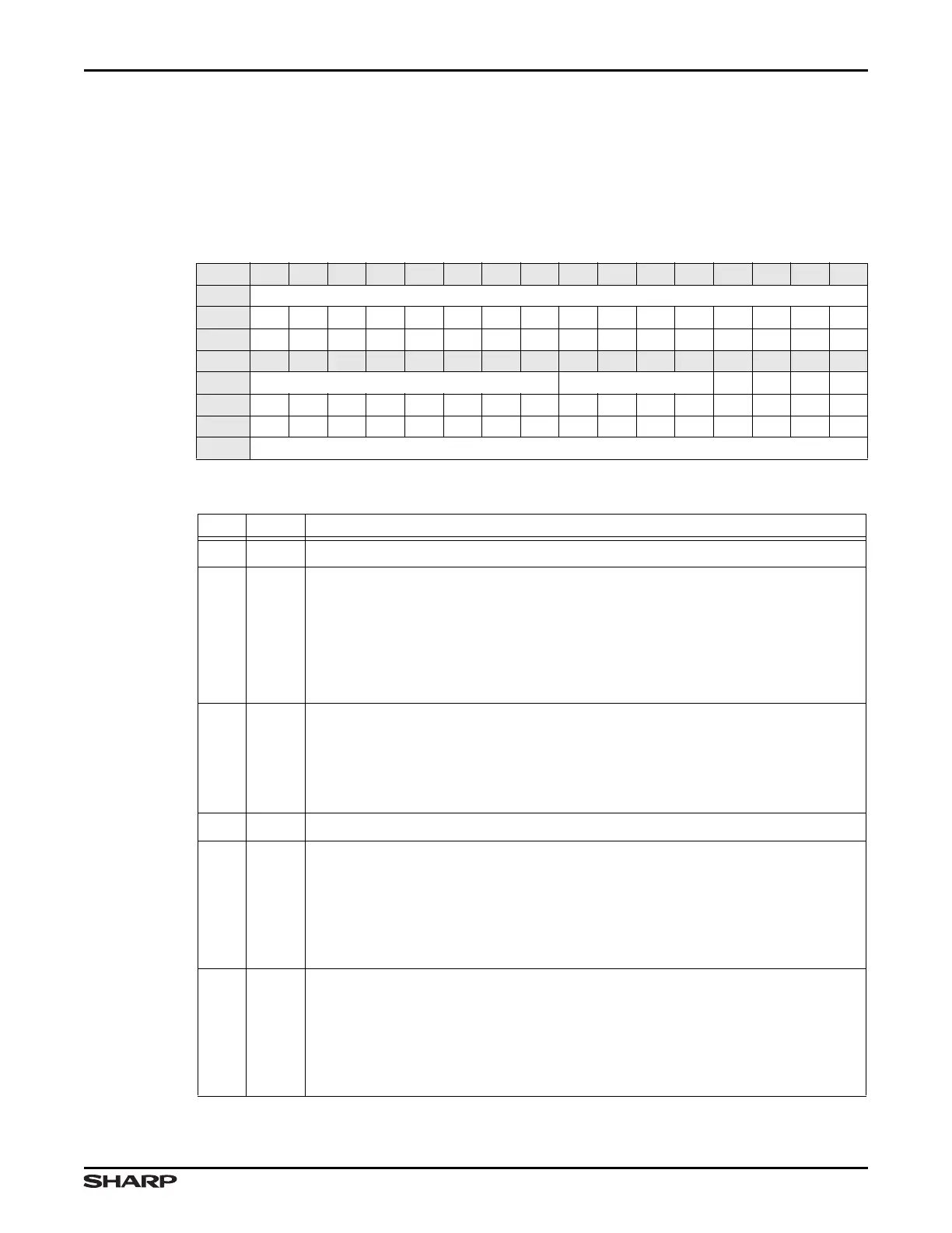
The WDT control register, described in Table 19-2 and Table 19-3 enables and disables
the WDT, and specifies the timeout period and interrupt response.
Table 19-2. CTL Register
BIT 31 30 29 28 27 26 25 24 23 22 21 20 19 18 17 16
FIELD ///
RESET 0000000000000000
TYPE RO RO RO RO RO RO RO RO RO RO RO RO RO RO RO RO
BIT 15 14 13 12 11 10 9 8 7 6 5 4 3 2 1 0
FIELD /// TOP FRZ /// IF EN
RESET 0000000000000000
TYPE RO RO RO RO RO RO RO RO RW RW RW RW RO RW RW RW
ADDR 0xFFFE3000 + 0x00
Table 19-3. CTL Fields
BITS NAME DESCRIPTION
31:8 /// Reserved Reading this field returns 0. Write the reset value.
7:4 TOP
Timeout Period Program this field to select one of 16 possible values to load
into the WDT to determine the timeout, in HCLK cycles. The loaded value is
2
(TOP+16)
. For example:
• TOP = 0x0 results in a timeout period of 2
16
HCLK cycles
• TOP = 0xF results in a timeout period of 2
31
HCLK cycles
When a timeout period is programmed, the new value takes effect after a counter
reset command or after the count reaches 0.
3FRZ
Freeze Set this bit while the watchdog is enabled, to prevent clearing EN. Only
a System Reset can clear FRZ.
1 = When WDT is enabled, the EN bit is frozen and cannot be cleared (set to 0)
0 = WDT function is not frozen. (FRZ cannot be cleared by writing a 0 to this bit;
a 0 is only valid when this bit is read. FRZ is only cleared with a System Reset)
2 ///
Reserved Reading this bit returns invalid data. Write the reset value.
1IF
Interrupt First Program this bit to specify whether the first WDT timeout
generates an interrupt or a system reset:
1 = The first timeout generates an interrupt and restarts the WDT. If this interrupt
is not cleared by software or by a reset, the second timeout generates a
system reset. A system reset clears this interrupt.
0 = Each timeout generates a system reset
0EN
Enable Program this bit to enable or disable the WDT:
1 = Enables the WDT. The counter decrements. Timeouts generate interrupts or
system resets, depending on the setting of the IF field. To prevent interrupts
or system resets, the WDT must be periodically reset.
0 = Disables the WDT. The counter does not decrement. Because no timeouts
occur, the WDT generates no interrupts or system resets.