I
2
S Converter LH79524/LH79525 User’s Guide
10-16 Version 1.0
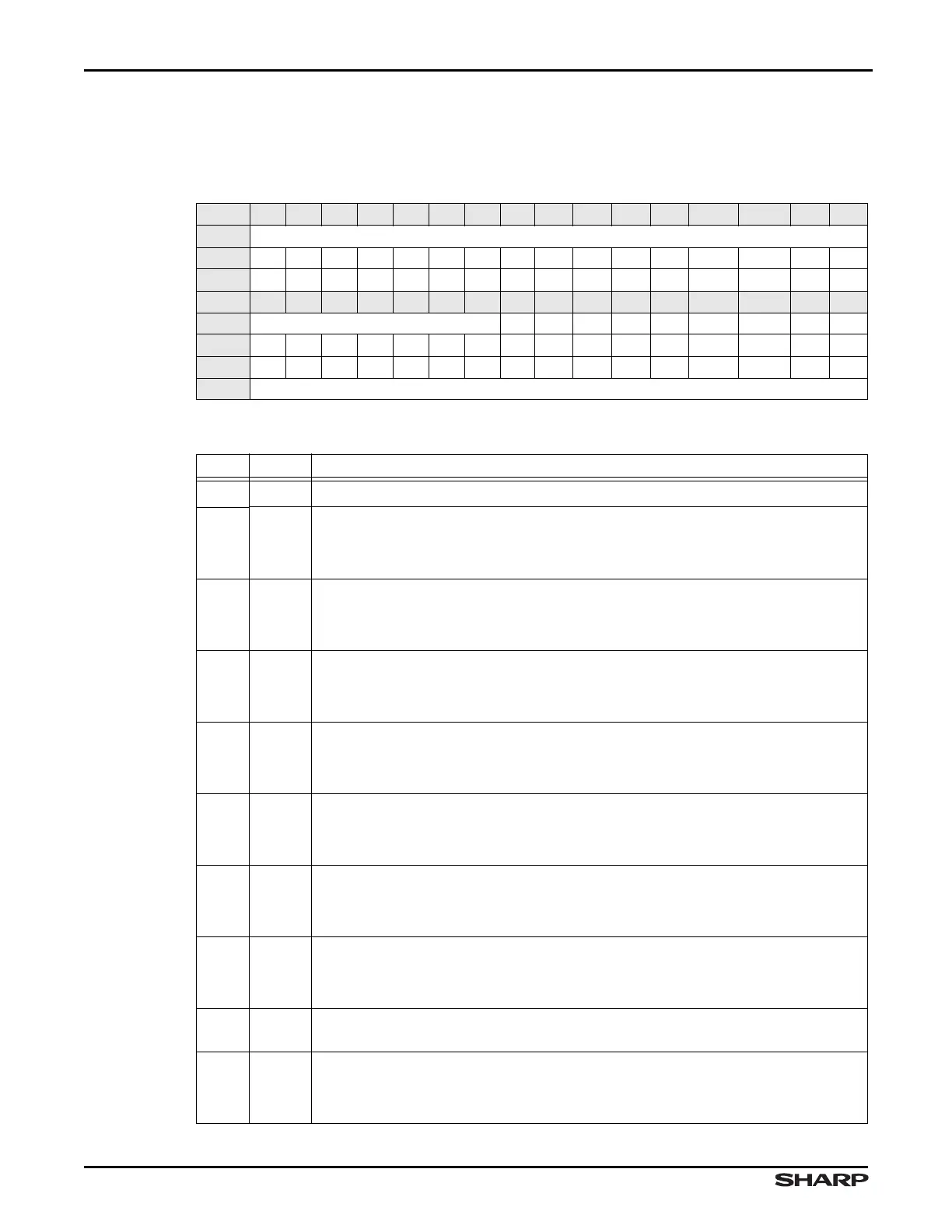
10.2.2.2 Status Register (STAT)
This register reports various I
2
S converter functions. All bits are read only.
Table 10-5. STAT Register
BIT 31 30 29 28 27 26 25 24 23 22 21 20 19 18 17 16
FIELD ///
RESET 000000000 0 0 0 0 0 0 0
RW RO RO RO RO RO RO RO RO RO RO RO RO RO RO RO RO
BIT 15 14 13 12 11 10 9 8 7 6 5 4 3 2 1 0
FIELD /// MS RFF RFE TFF TFE TXWS RXWS WS LBM
RESET 000000000 1 0 1 0 0 1 0
RW RO RO RO RO RO RO RO RO RO RO RO RO RO RO RO RO
ADDR 0xFFFC8000 + 0x004
Table 10-6. STAT Register Definitions
BITS NAME DESCRIPTION
31:9 /// Reserved Reading returns 0. Write the reset value.
8MS
Master or Slave Mode Select (From SSP CTRL1:MS bit)
1 = Device configured as slave
0 = Device configured as a master (default)
7RFF
Receive FIFO Full (From SSP SR:RFF bit)
1 = The Receive FIFO is full
0 = The Receive FIFO is not full
6RFE
Receive FIFO Empty
1 = The Receive FIFO is empty
0 = The Receive FIFO is not empty
5TFF
Transmit FIFO Full
1 = The Transmit FIFO is full
0 = The Transmit FIFO is not full
4 TFE
Transmit FIFO Empty (From SSP SR:TFE bit)
1 = The Transmit FIFO is empty
0 = The Transmit FIFO is not empty
3TXWS
WS value for TX word Applies only to I
2
S Transactions
1 = Next word written to SSP TX FIFO will have WS = 1
0 = Next word written to SSP TX FIFO will have WS = 0
2RXWS
WS value for RX word Applies only to I
2
S Transactions
1 = Next word read from SSP RX FIFO will have WS = 1
0 = Next word read from SSP RX FIFO will have WS = 0
1WS
WS value at pin This status bit is a real-time report of WS value at the pin.
Applies only to I
2
S Transactions
0LBM
I
2
S Loopback Mode Applies only to I
2
S Transactions
1 = Output of I
2
S Converter connected to input of I
2
S Converter internally
0 = Normal serial port operation enabled