LH79524/LH79525 User’s Guide Color Liquid Crystal Display Controller
Version 1.0 4-43
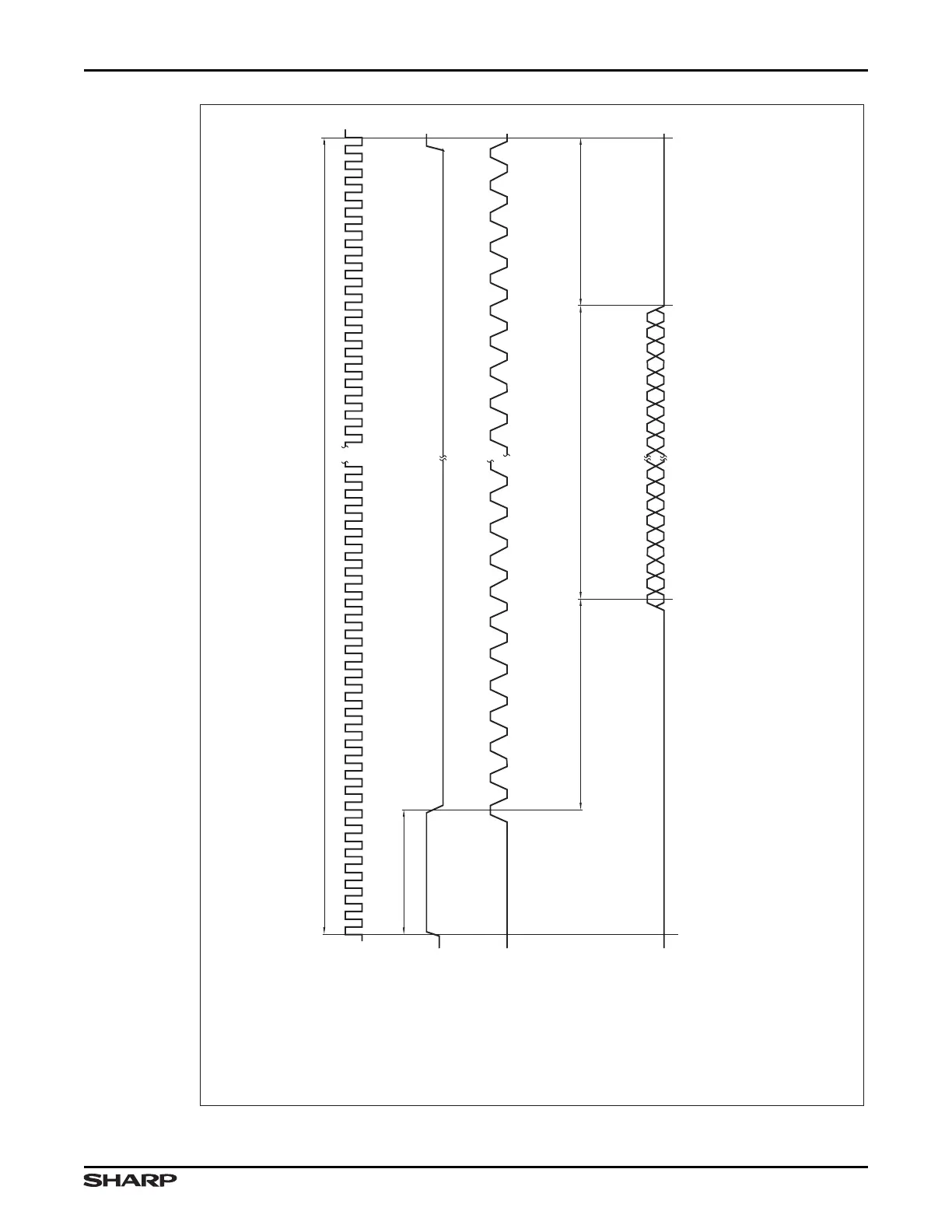
Figure 4-6. STN Horizontal Timing Diagram
1 STN HORIZONTAL LINE
CLCDC CLOCK
(INTERNAL)
APBPERIPHCLKCTRL1:LCD
CLKPRESCALE:LCDPS
LCDLP
(LINE
SYNCHRONIZATION
PULSE)
TIMING2:IHS
LCDDCLK
(PANEL CLOCK)
TIMING2:PCD
TIMING2:BCD
TIMING2:IPC
TIMING2:CPL
LCDVD[11:0] (LH79525)
LCDVD[15:0] (LH79524)
(PANEL DATA)
THE ACTIVE DATA LINES
WILL VARY WITH THE
TYPE OF STN PANEL:
4-BIT, 8-BIT, COLOR,
OR MONO
NOTES:
1. The CLCDC clock (from the RCPC) is scaled within the CLCDC and used to produce the LCDDCLK
output. CLCDC registers set timing (in terms of LCDDCLK pulses) to produce the other signals that
control an STN display.
2. The duration ot the LCDLP signal is controlled by TIMING0:HSW (the HSW bit field in the TIMING0 Register).
3. The polarity of the LCDLP signal is set by TIMING2:IHS.
TIMING0:HSW
TIMING0:HBP 16 × (TIMING0:PPL+1)
D001 D002 D....
ONE 'LINE' OF LCD DATA
DNNN
TIMING0:HFP
HORIZONTAL
BACK PORCH
HORIZONTAL
FRONT PORCH
ENUMERATED
IN 'LCDDCLKS'
ENUMERATED
IN 'LCDDCLKS'
LH79525-3
LCDDCLK IS
SUPPRESSED
DURING LCDLP