LH79524/LH79525 User’s Guide I
2
S Converter
Version 1.0 10-9
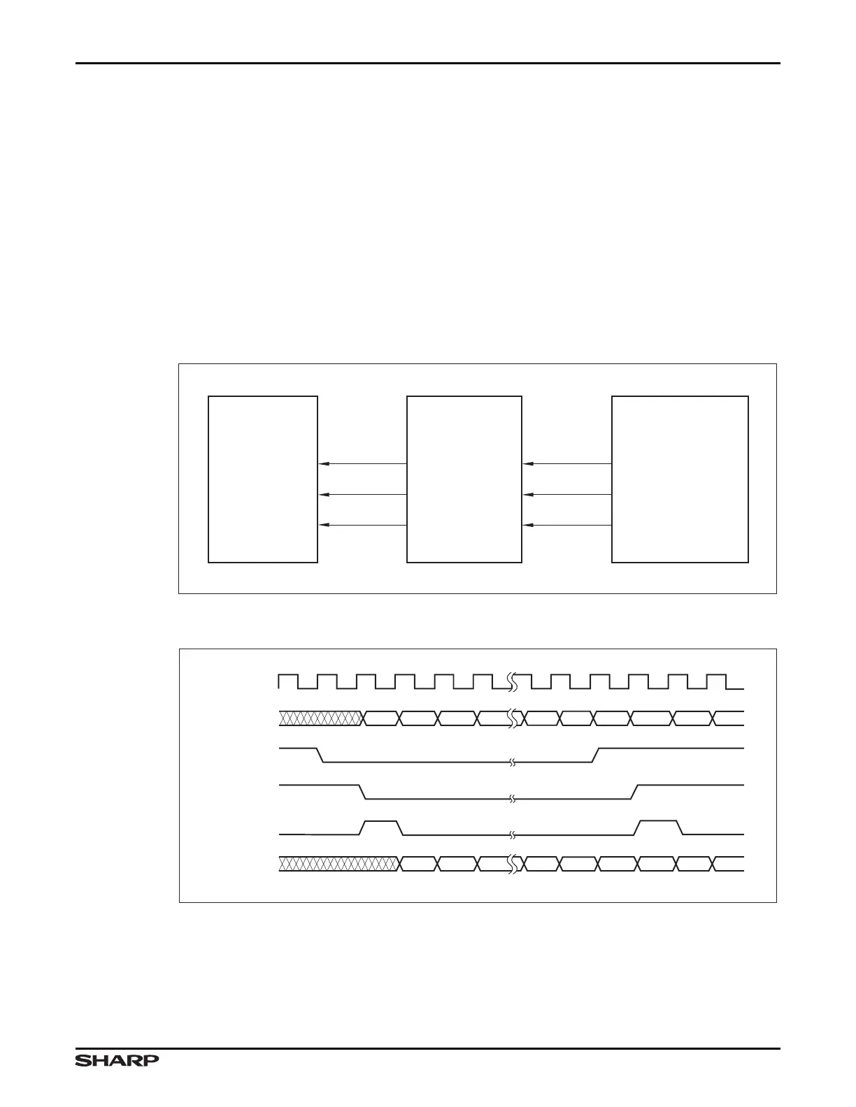
10.1.4.2 Slave Mode Reception
During Slave Mode reception, the I
2
S converter receives its clock (PB3/SSPCLK/I2SCLK),
frame input (PB2/SSPFRM/I2SWS) and data (PB4/SSPRX/I2SRXD/UARTRX0/
UARTIRRX0) from the external CODEC. The slave mode clock received by the SSP
is the I
2
S slave mode clock input, PB3/SSPCLK/I2SCLK, inverted as indicated by the
CTRL:CLKINV bit.
The received frame is converted to a pulse and sent to the SSP. This conversion
is accomplished by generating a pulse to the SSP for every edge detected on
PB2/SSPFRM/I2SWS. If WSDEL is 0, the pulse is delayed by one clock.
The data received by the I
2
S converter from the external CODEC is delayed by one clock
and sent to the SSP on SSPRXD.
Figure 10-11. I
2
S Slave Mode Reception Block Diagram
Figure 10-12. I
2
S Slave Mode Reception Timing Diagram
LH79525-10
SSP
(SLAVE)
EXTERNAL CODEC
(MASTER)
I2SCLKIN
I
2
S CONVERTER
(SLAVE)
I2SFSSIN
SCK
WS
SD
I2SRXD
SSPCLKIN
SSPFSSIN
SSPRXD
MSB1 14 13 12 2 13141 LSB1 LSB2
MSB1 14 13 3 2 141 LSB1 LSB2
I2SFSSIN
(WSDEL = 0)
I2SFSSIN
(WSDEL = 1)
SSPRXD
I2SCLKOUT
I2SRXD
SSPFSSIN
LH79525-102