Analog-to-Digital Converter/Brownout Detector LH79524/LH79525 User’s Guide
2-26 Version 1.0
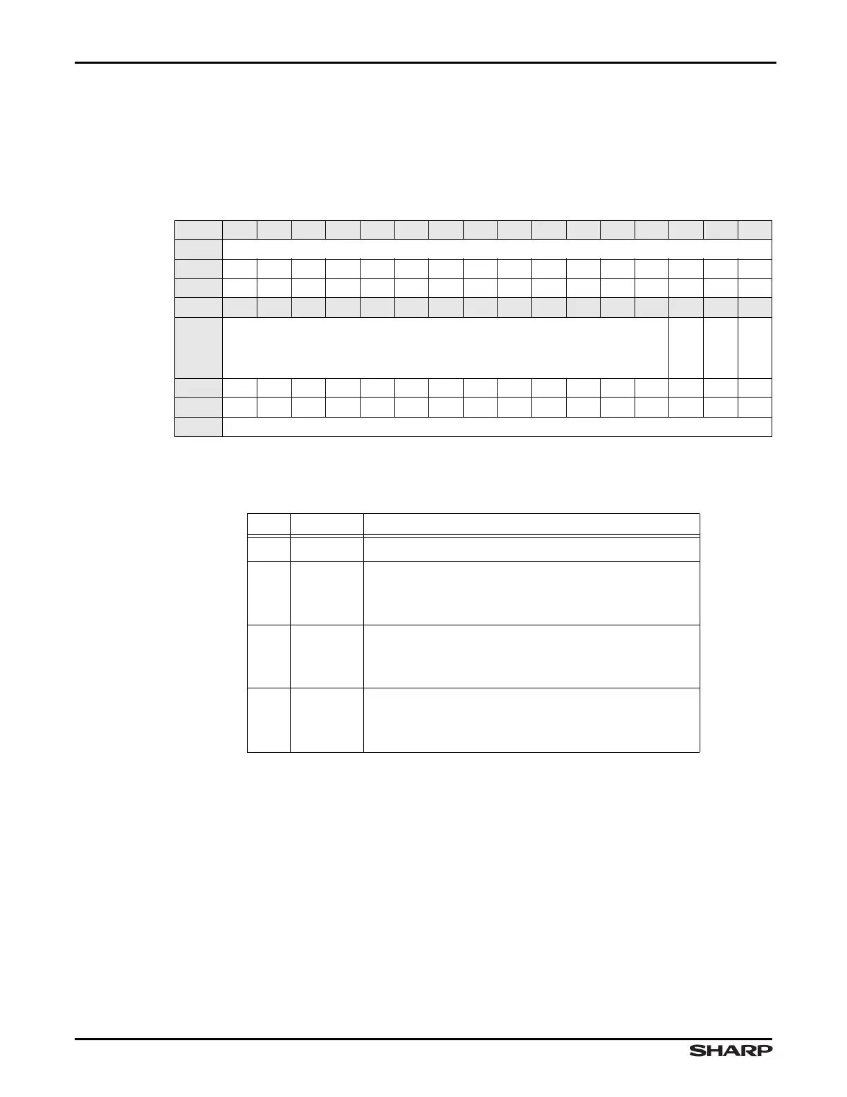
2.2.2.14 Interrupt Clear Register (IC)
IC is the Interrupt Clear Register. Bits [2:0] of this Write Only register correspond to the
three latched interrupts.Writing a 1 to a bit clears the corresponding interrupt; writing a 0
to a bit has no effect. This register is self-clearing.
NOTE: The reset value of this register’s bits is indeterminate.
Table 2-29. IC Register
BIT 31 30 29 28 27 26 25 24 23 22 21 20 19 18 17 16
FIELD ///
RESET ————————————————
RW WO WO WO WO WO WO WO WO WO WO WO WO WO WO WO WO
BIT 15 14 13 12 11 10 9 8 7 6 5 4 3 2 1 0
FIELD ///
BOIC
PENIC
EOSINTC
RESET ————————————————
RW WO WO WO WO WO WO WO WO WO WO WO WO WO WO WO WO
ADDR 0xFFFC3000 + 0xB0
Table 2-30. IC Fields
BITS NAME DESCRIPTION
31:3 /// Reserved Reading returns 0. Write the reset value.
2BOIC
Brown-Out Interrupt Clear
1 = Clears BROWNOUTINTR.
0 = Do not clear BROWNOUTINTR
1 PENIC
Pen Interrupt Clear
1 = Clears PENIRQ
0 = Do not clear PENIRQ
0EOSINTC
End of Sequence Interrupt Clear
1 = Clears EOSINTR
0 = Do not clear EOSINTR