LH79524/LH79525 User’s Guide UARTs
Version 1.0 16-15
16.3.2.7 Line Control Register (UARTLCR_H)
UARTLCR_H is the Line Control Register. This register is used to configure the UARTs.
The contents of the UARTLCR_H Register are not updated until transmission or reception
of the current character is complete. Table 16-21 is a truth table for the SPS, EPS, and
PEN bits of the UARTLCR_H Register.
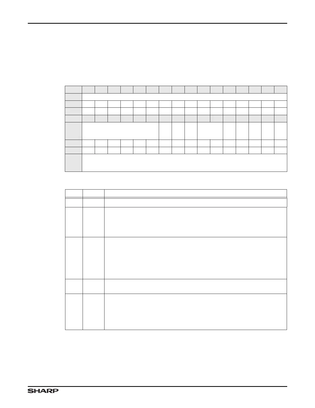
Table 16-19. UARTLCR_H Register
BIT 31 30 29 28 27 26 25 24 23 22 21 20 19 18 17 16
FIELD ///
RESET 0000000000000000
RW RO RO RO RO RO RO RO RO RO RO RO RO RO RO RO RO
BIT 15 14 13 12 11 10 9 8 7 6 5 4 3 2 1 0
FIELD ///
9BIT
ADDTX
SPS
WLEN
FEN
STP2
EPS
PEN
BRK
RESET 0000000000000000
RW RO RO RO RO RO RO RW RW RW RW RW RW RW RW RW RW
ADDR
UART 0: 0xFFFC0000 + 0x02C
UART 1: 0xFFFC1000 + 0x02C
UART 2: 0xFFFC2000 + 0x02C
Table 16-20. UARTLCR_H Fields
BIT NAME DESCRIPTION
31:10 /// Reserved Reading returns 0. Write the reset value.
99BIT
Nine-bit Mode Enable Use this bit to enable Nine-bit Mode.
1 = Nine-bit Mode enabled; characters are tagged during transmission as ad-
dress or data and checked during reception for address or data
0 = Nine-bit Mode disabled
8 ADDTX
Transmit Address This bit allows tagging characters in the UARTDR. Not
used and ignored if Nine-bit MODE ENABLE = 0.
During Nine-bit Mode (9BIT = 1):
1 = The next character written to UARTDR is tagged as an address. This bit is
automatically cleared when UARTDR is written.
0 = The next character written to UARTDR is tagged as data.
7SPS
Stick Parity Select Bits [7], [2], and [1] work together to set up the parity. See
Table 16-21.
6:5 WLEN
Word Length Indicates the number of data bits transmitted or received in a frame.
00 = 5 bits
01 = 6 bits
10 = 7 bits
11 = 8 bits