Color Liquid Crystal Display Controller LH79524/LH79525 User’s Guide
4-22 Version 1.0
4.5.3.2 Vertical Timing Panel Control Register (TIMING1)
The TIMING1 Register controls the:
• Number of Lines-Per-Panel (LPP)
• Vertical Synchronization Pulse Width (VSW)
• Vertical Front Porch (VFP) period
• Vertical Back Porch (VBP) period
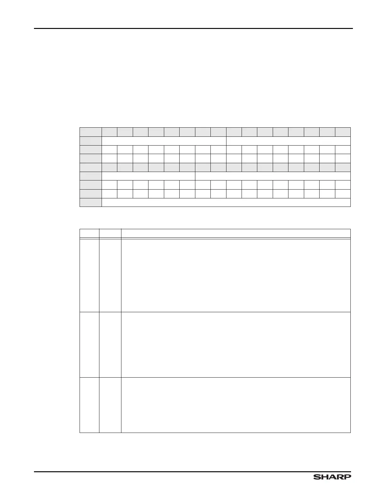
Table 4-16. TIMING1 Register
BIT 31 30 29 28 27 26 25 24 23 22 21 20 19 18 17 16
FIELD VBP VFP
RESET 0000000000000000
RW RW RW RW RW RW RW RW RW RW RW RW RW RW RW RW RW
BIT 15 14 13 12 11 10 9 8 7 6 5 4 3 2 1 0
FIELD VSW LPP
RESET 0000000000000000
RW RW RW RW RW RW RW RW RW RW RW RW RW RW RW RW RW
ADDR 0xFFFF4000 + 0x04
Table 4-17. TIMING1 Fields
BIT NAME DESCRIPTION
31:24 VBP
Vertical Back Porch VBP defines the number of inactive lines at the start of a frame,
after the vertical synchronization period (after the framing pulse, LCDFP, is de-asserted).
The VBP bit field specifies the number of horizontal line-clocks (LCDLP) inserted at the
beginning of each frame. The value in the VBP bit field can generate from 0 to 255
additional line-clock cycles.
TFT modes: The VBP delay begins after the vertical synchronization signal for the
previous frame (LCDFP) has been deasserted.
STN modes: Program to zero. The vertical back porch is not programmable and always a
duration of zero. Programming any other value other than zero will have no effect.
23:16 VFP
Vertical Front Porch VFP defines the number of inactive lines at the end of a frame, be-
fore the vertical synchronization period (before the framing pulse, LCDFP, is asserted).
VFP specifies the number of horizontal line-clocks (LCDLP) inserted at the end of each
frame. The value in the VFP bit field can generate from 0 to 255 line-clock cycles.
TFT modes: The vertical synchronization signal (LCDFP) is asserted after the VFP delay
has expired.
STN modes: Program small value. As higher values are programmed, the contrast of the
display will be reduced.
15:10 VSW
Vertical Synchronization (Pulse) Width
TFT Modes: VSW is the width of the LCDFP signal. VSW is specified in terms of the number
of horizontal synchronization lines (LCDLP pulses).
VSW = (LCDLP Periods) – 1
STN modes: Program to 0. The vertical sync pulse width is not programmable and always
a duration of 1 line. Programming any other value than zero will led to unexpected behavior.