LH79524/LH79525 User’s Guide Timers
Version 1.0 15-15
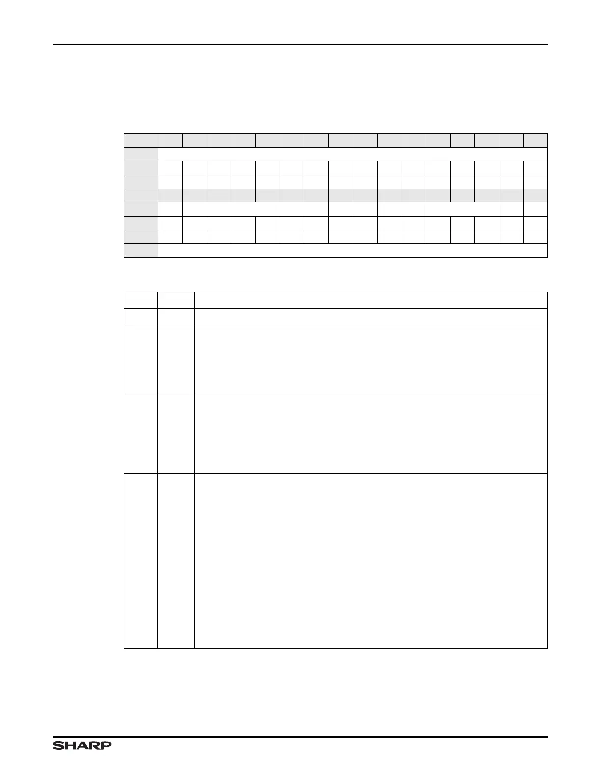
15.2.2.8 Timer 1 Control Register (CTRL1)
This register allows programming various functions, including PWM Mode, clock selection,
and starting/stopping Timer 1.
Table 15-18. CTRL1 Register
BIT 31 30 29 28 27 26 25 24 23 22 21 20 19 18 17 16
FIELD ///
RESET 0000000000000000
RW RO RO RO RO RO RO RO RO RO RO RO RO RO RO RO RO
BIT 15 14 13 12 11 10 9 8 7 6 5 4 3 2 1 0
FIELD /// PWM TC CMP1 CMP0 CAPB CAPA SEL CS CCL
RESET 0000000000000000
RW R RWRWRWRWRWRWRWRWRWRWRWRWRWRWRW
ADDR 0xFFFC4000 + 0x30
Table 15-19. CTRL1 Register Definitions
BITS NAME DESCRIPTION
31:15 /// Reserved Reading this field returns 0. Write the reset value.
14 PWM
PWM Output This bit allows the use of CTCMP1A as a PWM output. This is
done by programming this bit as well as other bits in this register. Refer to
Section 15.1.3 for a complete explanation and an example.
0 = Output CTCMP1A is normal and works only with the T0CMP1 Register.
1 = Output CTCMP1A is in PWM Mode.
13 TC
Timer 1 Operation This bit determines whether Timer 1 counter is to operate
as either a free running counter or as an interval timer. When 1, the counter
clears upon matching CMP1 for Timer 1. This operation is only available with the
CMP1 Register for Timer 1. Refer to Section 15.1.1 for a complete explanation.
0 = Inhibit counter clear (operates as free running counter).
1 = Clear counter when CNT1 for Timer 1 matches T1CMP1 for Timer 1.
12:11 CMP1
Output Value Select Timer/Counter Operation: Programs the value (when a
compare match occurs) output on the CTCMP1B pin when the CNT1 Register
matches T1CMP1.
00 = No change occurs to CTCMP1B
01 = Output 0 to CTCMP1B
10 = Output 1 to CTCMP1B
11 = Toggle the output to CTCMP1B
PWM Operation:
00 = Invalid
01 = Active HIGH PWM output polarity
10 = Active LOW PWM output polarity
11 = Invalid
IMPORTANT: CMP1 and CMP0 must be programmed to the same polarity.