LH79524/LH79525 User’s Guide I
2
S Converter
Version 1.0 10-5
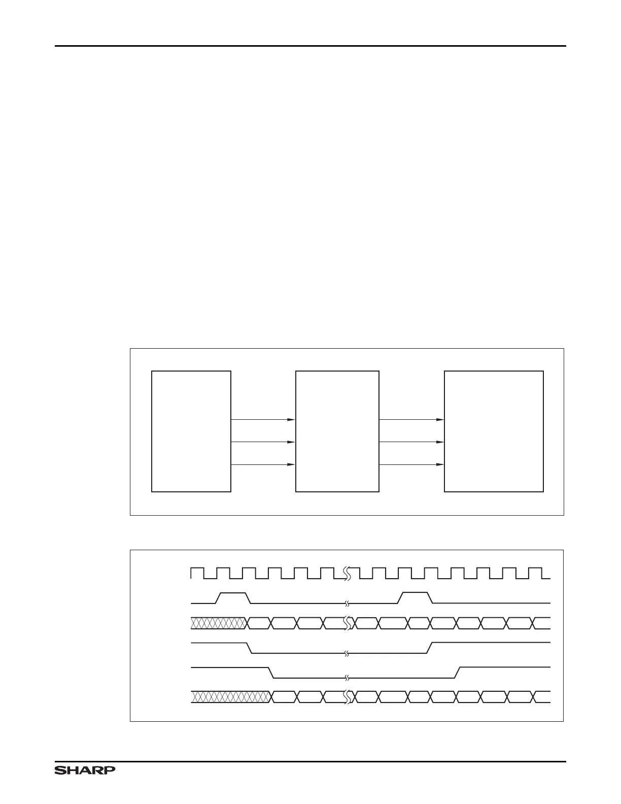
10.1.3 Transmission
10.1.3.1 Master Mode Transmission
During Master Mode transmission, the I
2
S converter supplies the clock, frame output, and
data (on the PB5/SSPTX/I2STXD/UARTTX0/UARTIRTX0 pin) to the external CODEC.
The Master Mode clock is the SSP master mode clock, SSPCLKOUT, inverted as indi-
cated by the CTRL:CLKINV bit.
The SSP frame output pulse is converted to a level to generate PB2/SSPFRM/I2SWS. If
WSDEL is set to 1, then PB2/SSPFRM/I2SWS is delayed by one clock so that it transitions
with the MSB of the transmitted data.
The data to be transmitted is received by the I
2
S converter from the SSP. It is delayed by
one clock and then transmitted on the PB5/SSPTX/I2STXD/UARTTX0/UARTIRTX0 pin.
Note that when in master mode, the I
2
S Converter requires that the SSP operate in TI con-
tinuous mode. If the transmit FIFO is starved, the SSP will operate in single-word transfer
mode in which is stops generating SSPCLKOUT and SSPFSSOUT as soon as the transfer
of the last word in the FIFO has completed. The I
2
S Converter needs these signals to per-
form its conversion.
Figure 10-5. I
2
S Master Mode Transmission Block Diagram
Figure 10-6. I
2
S Master Mode Transmission Timing Diagram
LH79525-95
SSP
(MASTER)
EXTERNAL CODEC
(SLAVE)
I2SCLKOUT
I
2
S CONVERTER
(MASTER)
I2SFSSOUT
SCK
WS
SD
I2STXD
SSPCLKOUT
SSPFSSOUT
SSPTXD
I2SFSSOUT
(WSDEL = 0)
I2SFSSOUT
(WSDEL = 1)
I2SCLKOUT
SSPFSSOUT
SSPTXD
MSB2MSB1
14 13
MSB1 14 13
12
21
321
14 13 12
14 13 12
11
LSB1
MSB2LSB1
I2STXD
LH79525-96