LH79524/LH79525 User’s Guide Ethernet MAC Controller
Version 1.0 6-5
Each Receive Buffer Descriptor List entry comprises two words. The first word contains only
the address of the receive buffer; the second word contains the receive status. If the length
of a receive frame exceeds the buffer length, the status word for the used buffer is written
with zeroes except for the Start Of Frame bit and the offset bits, if appropriate. A 1 in bit zero
of the address field indicates that the buffer has been used. The receive buffer manager then
reads the location of the next receive buffer and fills that with receive frame data. The final
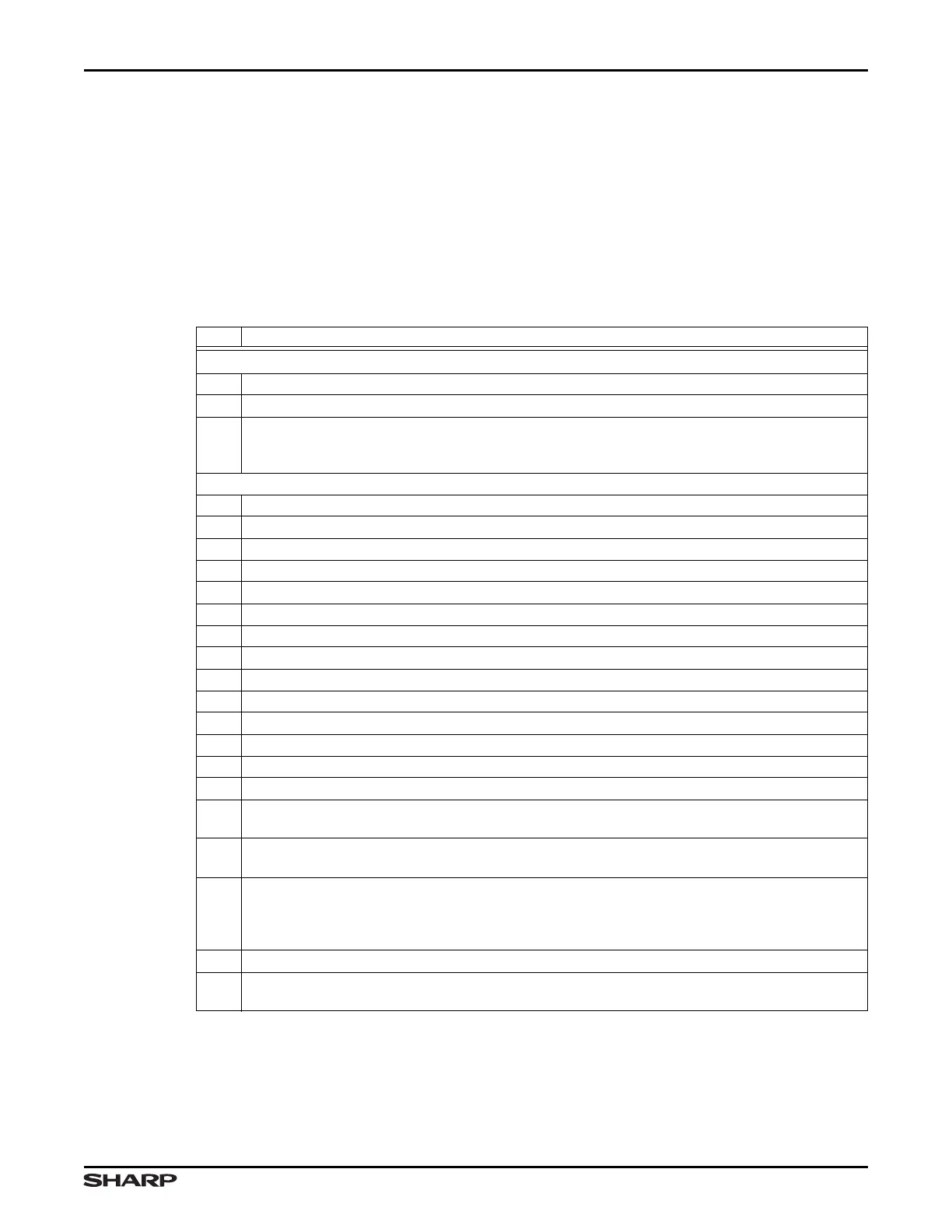
buffer descriptor status word contains the Complete Frame status. Table 6-1 provides the
details of the Receive Buffer Descriptor List. For each status bit, 1 = TRUE and 0 = FALSE.
Table 6-1. Receive Buffer Descriptor LIst
BIT DESCRIPTION
WORD 0
31:2 Start Address Address of the beginning of buffer
1 Wrap A 1 indicates the last descriptor in receive buffer descriptor list.
0
Ownership Needs to be 0 for the Ethernet MAC to write data to the receive buffer. The Ethernet
MAC sets this to 1 once it has successfully written a frame to memory. Software must clear this bit
before the buffer can be used again.
WORD 1
31 Global All Ones Broadcast Address Detected
30 Multicast Hash Match
29 Unicast Hash Match
28 External Address Match
27 Reserved Reading returns 0. Write the reset value.
26 Specific Address Register 1 Match
25 Specific Address Register 2 Match
24 Specific Address Register 3 Match
23 Specific Address Register 4 Match
22 Type ID Match
21 VLAN Tag Detected Type ID 0x8100
20 Priority Tag Detected Type ID 0x8100 and null VLAN identifier
19:17 VLAN Priority Only valid if bit 21 is set
16 Concatenation Format Indicator Only valid if bit 21 is 1
15
End Of Frame When 1, the buffer contains the end of a frame. If end of frame is not 1 then the only
other valid status bits are 12, 13, and 14.
14
Start Of Frame When 1 the buffer contains the start of a frame. If both bits 15 and 14 are 1, the
buffer contains an entire frame.
13:12
Receive Buffer Offset Indicates the number of bytes by which the data in the first buffer is offset
from the word address. Updated with the current values of the network configuration register. If Jum-
bo Frame Mode is enabled through NETCONFIG:JUMBOFRM, these bits are used as the most-sig-
nificant bits of Length Of Frame.
11 Reserved Reading returns 0. Write the reset value.
10:0
Length Of Frame Length includes FCS (if selected). Bits 13:12 are also used if Jumbo Frame Mode
is selected.