I
2
C Module LH79524/LH79525 User’s Guide
9-8 Version 1.0
9.2.2.2 I
2
C Slave Address Register (ICSAR)
Software programs this register with the unit address used by the I
2
C Module when in
Slave mode. In 7-bit addressing mode, the entire address is contained in this register. In
7-bit mode, bit 0 is not used.
In 10-bit addressing mode, this register holds the lower 8 address bits; the upper 2 address
bits and the R/W bit are in the ICUSAR register. This register is not used in Master mode.
3 SPEED
Fast/Standard Speed Use this bit to set the transaction speed of the I
2
C Module.
1 = Fast interface speed (400 kbit/s)
0 = Standard interface speed (100 kbit/s)
2I2CEN
I
2
C Enable This bit turns the I
2
C Module on and off.
1 = I
2
C Module is enabled
0 = I
2
C Module is disabled (SCL and SDA are not driven)
1:0 MODE
I
2
C Module Mode The I
2
C Module Mode field sets the operating mode of the
I
2
C Module.
11 = I
2
C Master Mode 10-Bit addressing
10 = I
2
C Master Mode 7-Bit addressing
01 = I
2
C Slave Mode 10-Bit addressing
00 = I
2
C Slave Mode 7-Bit addressing
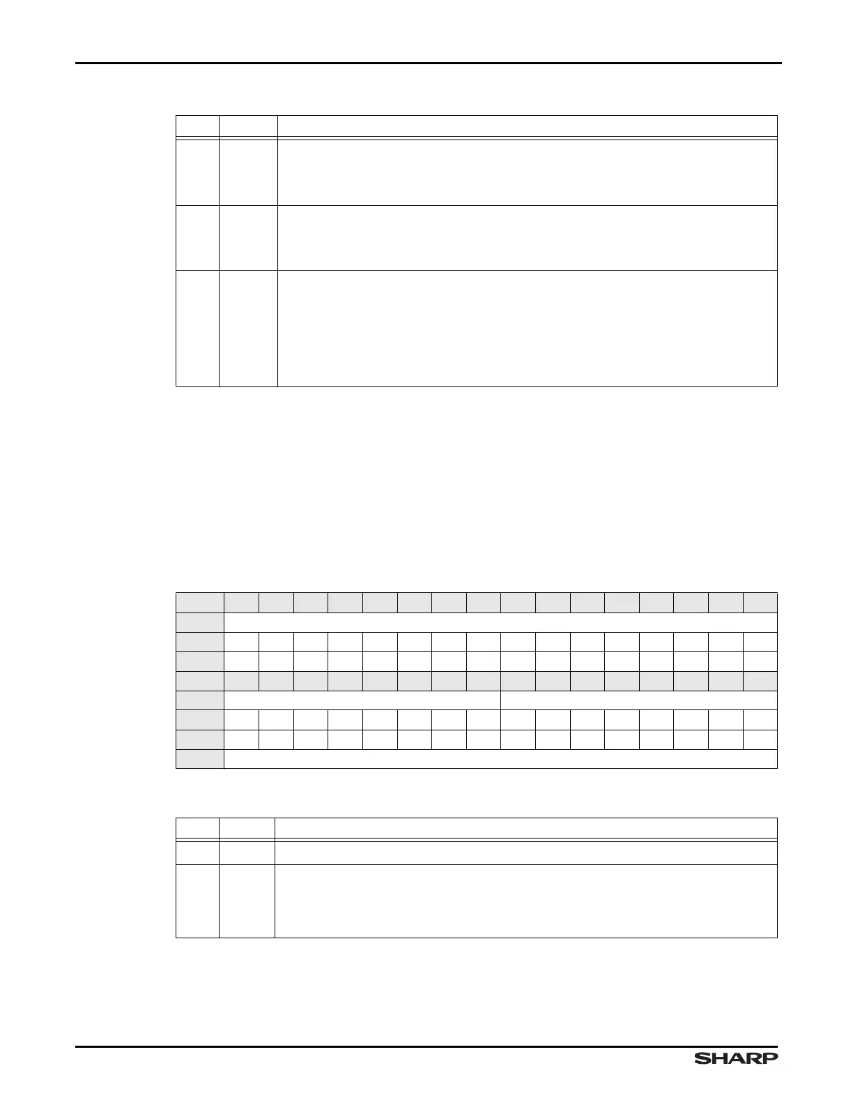
Table 9-6. ICSAR Register
BIT 31 30 29 28 27 26 25 24 23 22 21 20 19 18 17 16
FIELD ///
RESET 0000000000000000
TYPE RO RO RO RO RO RO RO RO RO RO RO RO RO RO RO RO
BIT 15 14 13 12 11 10 9 8 7 6 5 4 3 2 1 0
FIELD /// SLAD7
RESET 0000000000000000
TYPE RO RO RO RO RO RO RO RO RW RW RW RW RW RW RW RW
ADDR 0xFFFC5000 + 0x04
Table 9-7. ICSAR Fields
BITS NAME DESCRIPTION
31:8 /// Reserved Reading returns 0. Write the reset value.
7:0 SLAD7
Least-Significant 7 bits of Slave Address SLAD7[7:1] holds the lower 7 bits
of the I
2
C Module’s Slave address. In 10-bit addressing mode, SLAD7[7:0] holds
the lower 8 bits of the slave address. In 7-bit mode, SLAD7[7:1] contains the ad-
dress, and SLAD7[0] is not used.
Table 9-5. ICCON Fields (Cont’d)
BITS NAME DESCRIPTION