Timers LH79524/LH79525 User’s Guide
15-14 Version 1.0
15.2.2.7 Timer 0 Capture Registers (CAPn)
There are five CAPn Registers for Timer 0. They are designated:
• CAPA
• CAPB
• CAPC
• CAPD
• CAPE
Each register is a 16-bit, Read Only register. When a capture condition occurs, the con-
tents of the counter CNT0 are stored into the associated Capture Register. Capture Reg-
isters correspond to the input signals CTCAP0A through CTCAP0E, respectively. The
edge of the input signal used to trigger the capturing operation is selected with the
CMP_CAP_CTRL Register.
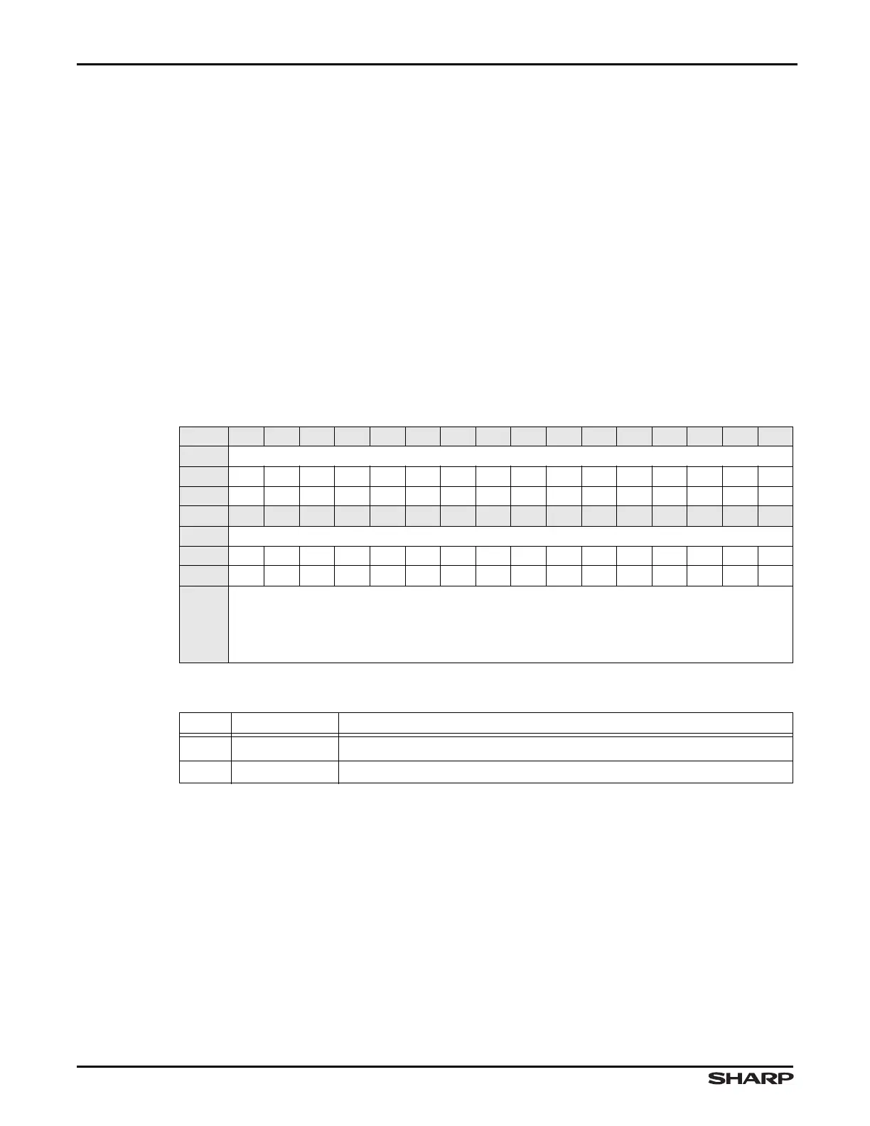
Table 15-16. CAPn Register
BIT 31 30 29 28 27 26 25 24 23 22 21 20 19 18 17 16
FIELD ///
RESET 0000000000000000
RW RO RO RO RO RO RO RO RO RO RO RO RO RO RO RO RO
BIT 15 14 13 12 11 10 9 8 7 6 5 4 3 2 1 0
FIELD CAPTURE0
RESET 0000000000000000
RW RO RO RO RO RO RO RO RO RO RO RO RO RO RO RO RO
ADDR
CAPA: 0xFFFC4000 + 0x1C
CAPB: 0xFFFC4000 + 0x20
CAPC: 0xFFFC4000 + 0x24
CAPD: 0xFFFC4000 + 0x28
CAPE: 0xFFFC4000 + 0x2C
Table 15-17. CAPn Register Definitions
BITS NAME DESCRIPTION
31:16 ///
Reserved Reading this field returns 0. Write the reset value.
15:0 CAPTURE0 Timer 0 Capture Register 16-bit capture register value.