LH79524/LH79525 User’s Guide Direct Memory Access Controller
Version 1.0 5-7
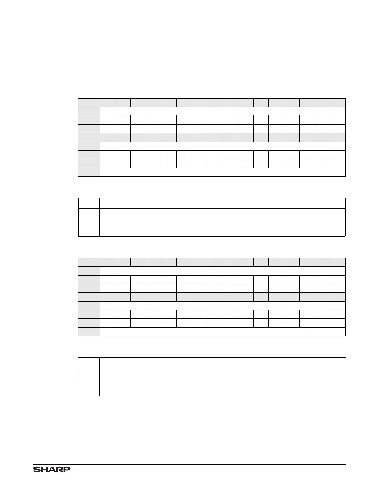
5.2.2.2 Destination Base Registers (DESTLO and DESTHI)
The two 16-bit Destination Base Register contain the 32-bit destination base address for
the next DMA transfer. When the DMA Controller is enabled, the contents of the Destina-
tion Base Address Registers load into the Current Destination Address Register.
Table 5-8. DESTLO Register
BIT 31 30 29 28 27 26 25 24 23 22 21 20 19 18 17 16
FIELD ///
RESET 0000000000000000
RW RO RO RO RO RO RO RO RO RO RO RO RO RO RO RO RO
BIT 15 14 13 12 11 10 9 8 7 6 5 4 3 2 1 0
FIELD DESTLO
RESET 0000000000000000
RW RW RW RW RW RW RW RW RW RW RW RW RW RW RW RW RW
ADDR DATASTREAM x BASE + 0x008
Table 5-9. DESTLO Fields
BITS NAME DESCRIPTION
31:16 /// Reserved Reading returns 0. Write the reset value.
15:0 DESTLO
Low Order Destination Address This field contains the lower 16-bits of the
address for the destination of data for the next DMA transfer.
Table 5-10. DESTHI Register
BIT 31 30 29 28 27 26 25 24 23 22 21 20 19 18 17 16
FIELD ///
RESET 0000000000000000
RW RO RO RO RO RO RO RO RO RO RO RO RO RO RO RO RO
BIT 15 14 13 12 11 10 9 8 7 6 5 4 3 2 1 0
FIELD DESTHI
RESET 0000000000000000
RW RW RW RW RW RW RW RW RW RW RW RW RW RW RW RW RW
ADDR DATASTREAM x BASE + 0x00C
Table 5-11. DESTHI Fields
BITS NAME DESCRIPTION
31:16 /// Reserved Reading returns 0. Write the reset value.
15:0 DESTHI
High Order Destination Address This field contains the upper 16-bits of the
address for the destination of data for the next DMA transfer.