Boot Controller LH79524/LH79525 User’s Guide
3-6 Version 1.0
3.1.2.2.1 NAND Flash Chip Select
Because of the hardware implementation of the NAND Flash signalling, the LH79524/
LH79525 chip select used for NAND Flash addressing must be nCS0 for booting; nCS1
cannot be used. Connect the nCS0 pin to the NAND Flash nCE input pin if that device is
used for booting. If the NAND Flash is not used for booting, it can be located in any chip
select domain.
3.1.3 Booting Using the I
2
C Interface
Booting can also be done using the I
2
C interface. When booting from I
2
C, the device
address that must be used is 0b1010000x. This address is not alterable. The Boot Con-
troller will always boot exactly 4Kbytes when using the I2C serial EEPROM.
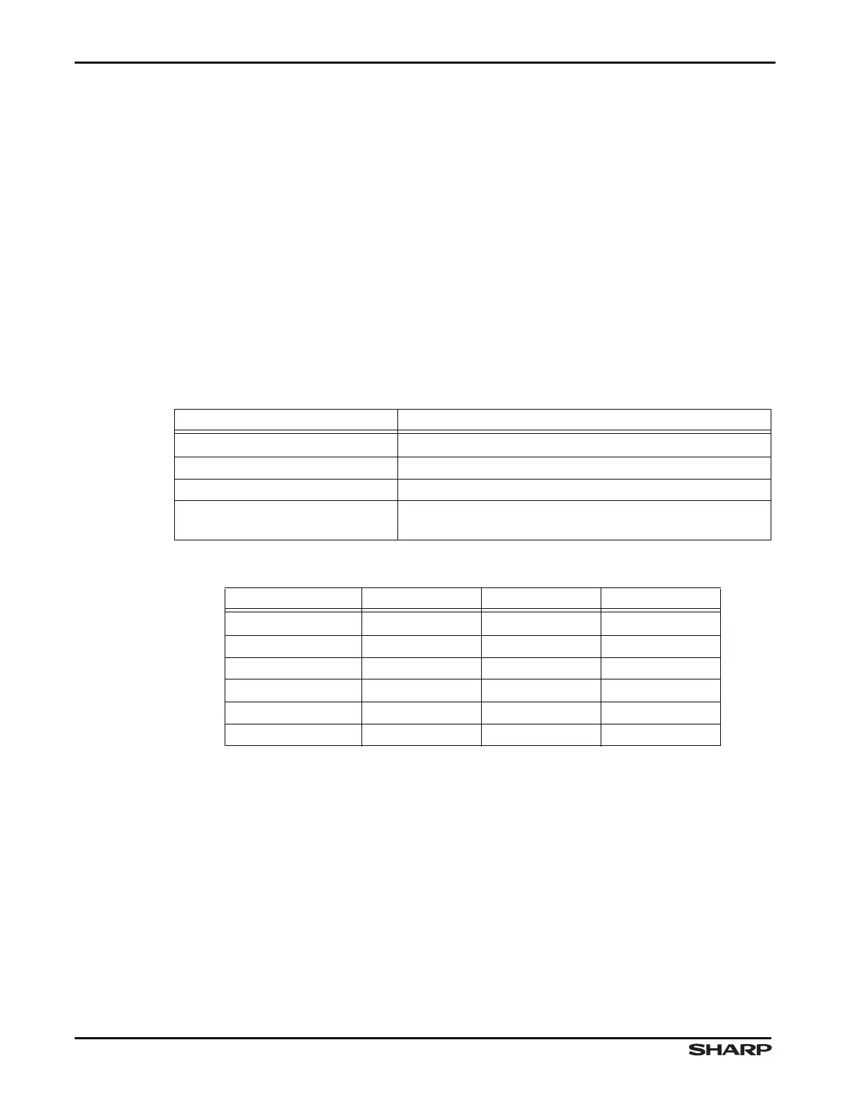
Interface parameters are shown in Table 3-4 and the list of supported devices is shown
in Table 3-5.
Table 3-4. Boot Parameters for I
2
C
PARAMETER VALUE
Communication Speed 400 kHz
Mode of SoC Master Mode
Addressing Mode 7 bit
I
2
C EEPROM Configuration
Slave, addressed at 0b1010000x, where x=0 for Writes and
x=1 for Reads
Table 3-5. Supported Devices
DENSITY ATMEL ST MICRO MICROCHIP
32Kbit (4K × 8) AT24C32 M24C32 24xx32
64Kbit (8K × 8) AT24C32 M24C64 24xx64
128Kbit (16K × 8) AT24C32 M24128 24xx128
256Kbit (32K × 8) AT24C32 M24256 24xx256
512Kbit (64K × 8) AT24C32 M24512 24xx512
1Mbit (128K × 8) AT24C32 N/A N/A